Figure a pipelined floating-point combined adder/multiplier unit
pipeline of the floating point unit
reservation table
collision vector
multiple cycle pipeline
dynamic scheduling in pipeline
scoreboard bookeeping
Tomasulo
figure CDC6600 IBM360/91
A reservation table shows a timing diagram of a flow of data through the functional unit. The reservation table is derived directly from the pipeline design. It is used to decide when to launch an operation into the pipeline. Both operations cannot use the same unit at the same time. A collision vector represents the collision information. Position i contains a bit that indicates whether or not a new operation can be launched i units after the first operation has been started.
(a) 1 1 0 0 0 0 (b) 1 0 0 0 0 0 0 0
Figure Collision vectors of (a) multiplication (mul follows by mul) (b) addition (add, add)
Figure an example of multi step pipeline
Assume there are two separate register sets : FP and Integer. This simplifies the pipeline control as it reduces hazard detection such as overlapping FP and Integer operations, except for load/store FP and movement between FP/Integer registers. Integer unit handles load/store to both register sets. Assume EX stage is repeated many times to do these operations. No other instruction using functional unit may issue until the previous instruction leaves EX. If an instruction cannot proceed to the EX stage, the entire pipeline behind that instruction will be stalled (to avoid this stall, we need the capability to do out-of-order issue, the topic of next section). The following steps are required to issue a new floating-point instruction :
DIVF F0 F2 F4Assume DIVF takes longer than SUBF to complete. The SUBF will complete first and writes its result before the DIVF. This hazard must be detected and ensure that the result is of executing instructions is correct.
SUBF F0 F8 F10
All the previous pipeline technique that we described use in-order instruction issue. If an instruction is stalled in the pipeline, no later instructions can proceed. When there are multiple functional units, these units could be idle. For example,
DIVF F0 F2 F4The SUBF cannot be issue because the dependence of ADDF on DIVF (RAW on F0). Yet, the SUBF does not depend on any instruction in the pipeline. If an instruction can be executed out-of-order this stall can be eliminated.
ADDF F10 F0 F8
SUBF F8 F8 F14
We can check data hazards in the ID stage. In order to let an instruction start its execution as soon as its operands is available, the instruction issuing process must be separated from the hazard checking. The pipeline will do out-of-order execution which implies out-of-order completion. We have to split the decode, execution stages into 3 stages :
Every instruction goes through the scoreboard which keeps all information necessary to detect all hazards. The scoreboard determines when an instruction can read its operands and begin execution. The scoreboard controls when an instruction can write its result into the destination register. All hazard detection and resolution is centralised in the scoreboard.
To illustrate the working of scoreboard let we assume S1 with scoreboard (S1s). Assume S1s has 2 FP multipliers, FP divide, FP add and Integer unit. Integer units handles all load/store, memory references, branches and integer operations. Each instruction goes through 4 steps, which replaces the pipeline stages, as follows:
Example, a scoreboard of S1s controls the execution of the following sequence of instructions:
LF F6 34(R2)The scoreboard has three parts:
LF F2 45(R3)
MULTF F0 F2 F4
SUBF F8 F6 F2
DIVF F10 F0 F6
ADDF F6 F8 F2
1. Instruction statusAssuming the execution of the floating-point functional units are : add is 2 clocks, multiply is 10 clocks and divide is 40 clocks. Each instruction that has issued, has an entry in the instruction status table. Once the instruction issues, the record of its operands is kept in the functional unit status table. See the figure, the instruction status says that
2. Functional unit status, each FU has the following fields2.1 Busy3. Register result status, which FU will write register.
2.2 Op, instruction to be performed
2.3 Dest , destination register
2.4 Src1, Src2, source registers
2.5 P1, P2, number of units producing Src1, Src2
2.6 R1, R2, ready flags for Src1, Src2; they are reset when new values are read so the scoreboard knows that the source operand has been read.
1) the first LF has completedThe instruction unit status says that
2) the second FL has completed but has not yet written its result.
3) the MULTF, SUBF and DIVF have issued but are stalled, waiting for their operands.
1) the first multiplier unit is waiting for the integer unit. (RAW on F2).
2) the add unit is waiting for the integer unit. (RAW on F2).
3) the divide unit is waiting for the first multiplier unit. (RAW on F0).
4) the ADDF is stalled due to structural hazard (FU Add is in used by SUBF).
Now assume the MULF and DIVF are proceeded and ready to write results.
There are RAW on
1) the second LF to MULTF and SUBF (on F2)There is a WAR between DIVF and ADDF on F6. There is a structural hazard on FU add for ADDF. The DIVF has not yet read its operands. The ADDF has read its operands and is in execution, it was waiting for SUBF (structural hazard). The ADDF cannot write its results because of WAR on F6.
2) MULTF to DIVF (on F0)
3) SUBF to ADDF (on F8)
Figure The scoreboard when MULTF and DIVF are ready to write results.
check funtional unit is not busy (functional units status)
and dest is not waiting for the result (register result status)
check busy field in FU = yes
check op field in FU = opcode
fill FU : Dest Src1 Src2
fill P1 P2 with the register result of Src1 Src2
check R1 R2 = not P1, not P2
write the name of FU to register result
Read operands
wait for R1 R2 until ready
read operands
set R1, R2 = No
P1, P2 = 0
Execution complete
wait until functional unit done
Write result
check WAR hazard
when other instruction has this instruction Dest
as Src1 or Src2
for all f
Src1(f), Src2(f) != Dest(FU)
AND
when other instruction has written the register R1, R2
R1 = Yes or R2 = Yes
wait until no harzard
set ready flag
for all f
if P1(f) = FU then R1(f) = Yes
if P2(f) = FU then R2(f) = Yes
reset register result
reset busy field of FU
end scoreboard bookeeping

Figure CDC6600 the first supercomputer.
Photo courtesy of Charles Babbage Institute, University of Minnesota.
Two other differences between scoreboard and Tomasulo are : first, hazard detection and execution control are distributed by each reservation station (in scoreboard it is centralised), second, results are passed directly to functional units rather than through registers. A common result bus allows all units waiting for an operand to be loaded simultaneously, this is called the common data bus (CDB).
The steps to execute an instruction :
Figure A CPU with two floating point functional units each with two reservation stations, and one load one store buffer
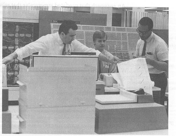
Figure IBM 360/91 it is unveiled
in 1966. Photo courtesy of IBM.