S2: A Hypothetical 32-bit Processor
version 3
This is a typical simple 32-bit CPU. It has three-address instruction
formats, with 32 registers and load/store access to memory. This document
presents only S2 assembly language view. It does not give details about
microarchitecture (such as pipeline).
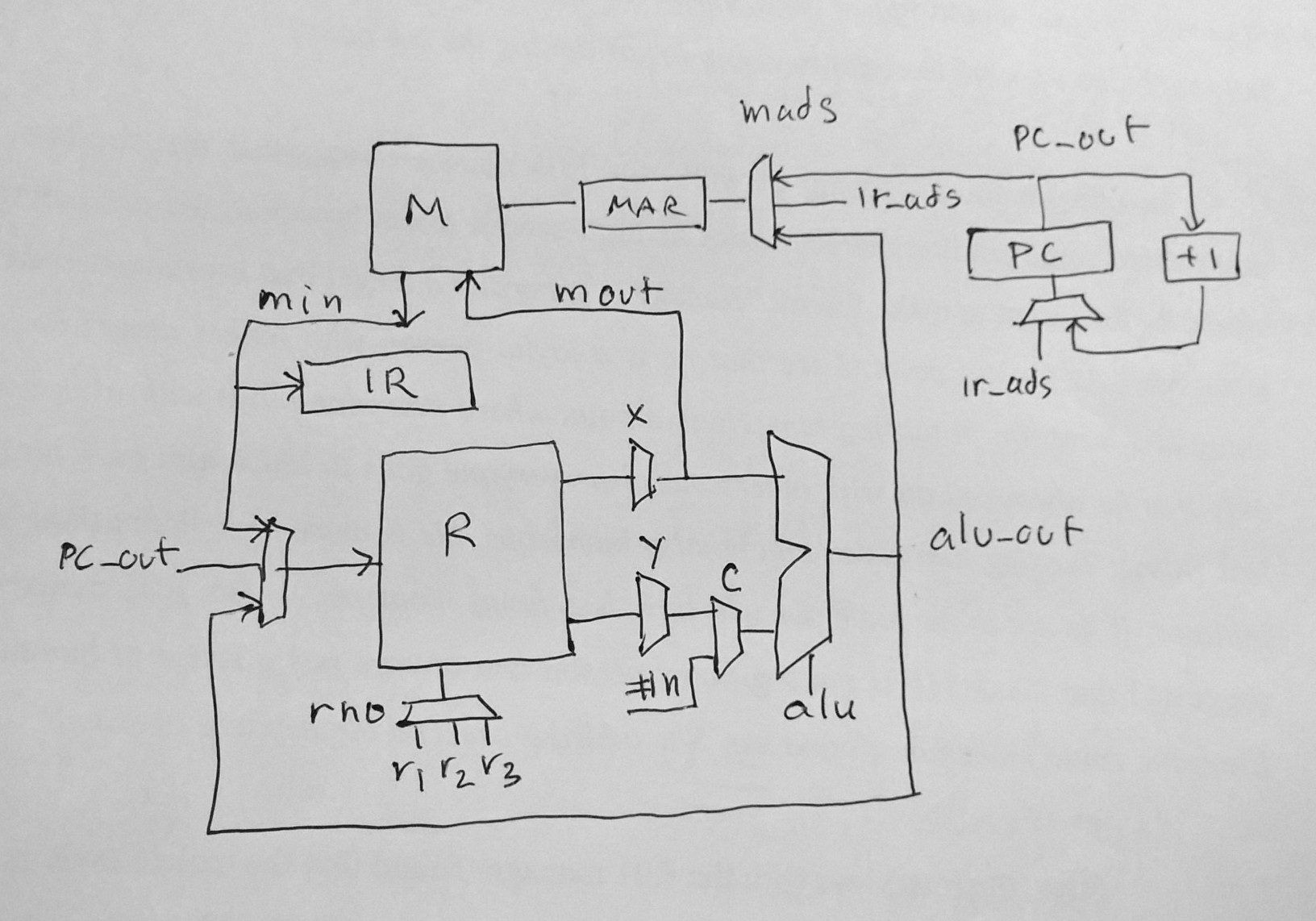
<Figure s2 microarchitecture>
S2 micro step
S2 has three-address instruction set. A general format of an
instruction (register to register operations) is:
op r1
r2 r3 means R[r1] = R[r2] op R[r3]
To pass values between memory and registers, load/store instructions are
used. Load transfers memory to register. Store transfers register to
memory. There are three addressing modes: absolute, displacement and index.
ld r1
ads R[r1] =
M[ads] absolute
ld r1 @10 r2 R[r2] = M[10+R[r2]]
displacement
ld r1 +r2 r3
R[r1] = M[R[r2]+R[r3]] index
st r1
ads M[ads] =
R[r1] absolute
st r1 @2 r2
M[10+R[r2]] = R[r2] displacement
st r1 +r2 r3
M[R[r2]+R[r3]] = R[r1] index
Instruction type
arithmetic:
add sub mul div mod
logic:
and or xor eq ne lt le gt ge shl shr
control:
jmp jt jf jal ret
data:
ld st push pop
Instruction meaning
false == 0
true != 0
R[0] always zero
Data
ld r1
ads R[r1] =
M[ads] load absolute
ld r1 @10 r2 R[r2] = M[10+R[r2]]
load displacement
ld r1 +r2 r3
R[r1] = M[R[r2]+R[r3]] load index
st r1
ads M[ads] =
R[r1] store absolute
st r1 @2 r2
M[10+R[r2]] = R[r2] store displacement
st r1 +r2 r3
M[R[r2]+R[r3]] = R[r1] store indexControl
jmp
ads pc = ads
jump
jt r1
ads if R[r1] != 0, pc = ads
jump if true
jf r1
ads if R[r1] == 0,
pc = ads
jump if false
jal r1
ads R[r1] = PC; PC = ads jump
and link, to subroutine
ret
r1
PC = R[r1]
return from subroutine
Arithmetic
two-complement integer arithmetic
add r1 r2 r3
R[r1] = R[r2] + R[r3]
add r1 r2 #n
R[r1] = R[r2] + sign extended n
sub r1 r2 ...
mul r1 r2 ...
div r1 r2 ...
mod r1 r2 ...
Logic (bitwise)
and r1 r2 r3
R[r1] = R[r2] bit-and R[r3]
and r1 r2 #n
R[r1] = R[r2] bit-and n
(sign extended)
or r1 r2
r3 R[r1] = R[r2] bit-or R[r3]
or r1 r2 #n
R[r1] = R[r2] bit-or n (sign extended)
xor r1 r2 r3
R[r1] = R[r2] bit-xor R[r3]
xor r1 r2
#n R[r1] = R[r2] bit-xor n
(sign extended)
eq r1 r2
r3 R[r1] = R[r2] == R[r3]
eq r1 r2
#n R[r1] = R[r2] == n
(sign extended)
. . .
shl r1 r2 r3
R[r1] = R[r2] << R[r3]
shl r1 r2 #n
R[r1] = R[r2] << #n
shr r1 r2 r3
R[r1] = R[r2] >> R[r3]
shr r1 r2 #n
R[r1] = R[r2] >> #n
Stack operation
To facilitate passing the parameters to a subroutine and also to save state
(link register) for recursive call, two stack operations are defined: push,
pop.
push r1
r2 R[r1]++; M[R[r1]] = R[r2] // push r2, r1 as stack pointer
pop r1
r2 R[r2] = M[R[r1]];
R[r1]-- // pop to r2,
r1 as stack pointer
Pseudo
Pseudo instructions are unlike other instructions, they are used mainly to
control the simulator and to perform input/output. Some pseudo
instructions are just like short-hand mnemonics, they are synthesized from
other real instructions.
trap r #n
special instruction, r pass parameter
trap r0 #0 stop simulation
trap r2 #1 print integer in R[r2]
R0 is always zero, many instructions can be synthesized using r0.
mov r1 r2
is or r1 r2 r0
mov r1 #n is add r1 r0 #n
Indirect address can be synthesized from index with r0.
ld r5 +r2 r0 load r5 with
indirect r2 R[5] = M[R[2]]
To complement a register, xor with 0xFFFFFFFF (-1) can be used.
not r1 r2
is xor r1 r2 #-1
R[r1] = complement R[r2]
Instruction format
op:6 r1:5 r2:5 d:16
(r1 dest, r2 source, d is sign extended, d can store {r3,ads,disp} )
Instructions are fixed length at 32 bits. There are 32 registers, with
R[0] always returns zero. The address space is 32-bit. Access to
memory is always on word boundary (no byte-access). Direct (absolute
address) is 16-bit or the first 64K words. Index and indirect access
can reach the whole 32-bit address space. Immediate value (d) is
16-bit. It is sign extended. The jump instructions (jmp,
jt, jf) have 16-bit absolute address. This format simplifies the instruction
encoding, instead of making the address bit as large as possible (see S21
for example of a realistic encoding), the format is restricted to one fixed
field format. This makes it easier to write tools (assembler,
simulator etc.). It is a compromise that works well for teaching
purpose.
Opcode encoding
0 nop
1 ld r1 ads
2
ld r1 @d ads
3 st r1
ads
4 st r1 @d ads
5 nop
6 jmp
ads
7 jal r1 ads
8
jt r1 ads
9 jf r1 ads
10 add r1 r2 #n
11 sub
r1 r2 #n
12 mul
r1 r2 #n
13 div
r1 r2 #n
14 and
r1 r2 #n
15 or
r1 r2 #n
16 xor
r1 r2 #n
17 eq
r1 r2 #n
18 ne
r1 r2 #n
19 lt
r1 r2 #n
20 le
r1 r2 #n
21 gt
r1 r2 #n
22 ge
r1 r2 #n
23 shl
r1 r2 #n
24 shr
r1 r2 #n
25 mod r1 r2 #n
26..31 undefined
32 add r1 r2 r3
33 sub
r1 r2 r3
34 mul
r1 r2 r3
35 div
r1 r2 r3
36
and r1 r2 r3
37 or
r1 r2 r3
38 xor
r1 r2 r3
39 eq
r1 r2 r3
40 ne
r1 r2 r3
41 lt
r1 r2 r3
42 le
r1 r2 r3
43 gt
r1 r2 r3
44 ge
r1 r2 r3
45 shl
r1 r2 r3
46 shr
r1 r2 r3
47 mod
r1 r2 r3
48 ld r1 +r2 r3
49 st r1 +r2 r3
50 ret r1
51 trap r1 #n
52 push r1 r2 use
r1 as stack pointer
53 pop r1 r2
use r1 as stack pointer
Historical fact
S21 is an extension of S2 from 2007. This design is a result of my
collective experience in teaching assembly language to novice programmers
for many years. S2 has been used for teaching since 2001. S2
itself is an "extended" version of S1 (a 16-bit processor) which is used for
teaching since 1997.
To improve understandability of S2 assembly language, flags are not
used. Instead, new logical instructions that have 3-address are
introduced. They are similar to existing arithmetic
instructions. The result (true/false) is stored in a register.
Two conditional jumps are introduced "jt", "jf". They make use of the result
from logical instructions. To avoid the confusion between absolute
addressing and moving between registers, a "pseudo" instruction "mov" is
introduced, "ld r1 #n" is eliminated. Displacement addressing caused
difficulty to many students (similar to pointers in C language).
However, array index is simple to understand (may be aided by students'
experience in high level language programming).
The opcode format and assembly language format for S2 follow the tradition
"dest = source1 op source2" from classic machines such as PDP-11, VAX and
IBM S360.
Example programs
1. Add 1 to 10
s = 0
i = 0
while i <= 10
s = s + i
i = i + 1
use r1 as s, r2 as i, r3 as flag
mov r1 #0 ; s = 0
mov r2 #0 ; i = 0
:while
le r3 r2 #10 ; i <= 10
jf r3 exit
add r1 r1 r2 ; s = s + i
add r2 r2 #1 ; i = i + 1
jmp while
:exit
2. Sum all elements in an array. Assume the array is at 100,
size of array is n.
s = 0
i = 0
while i < n
s = s + ax[i]
i = i + 1
use r1 as s, r2 as i, r3 as base, r4 as ax[i], r5 as flag
mov r1 #0 ; s
= 0
mov r2 #0 ; i = 0
mov r3 #100 ; set base address
:while
lt r5 r2 #n ; i < n
jf r5 exit
ld r4 +r3 r2 ; ax[i]
add r1 r1 r4 ; s = s + ax[i]
add r2 r2 #1 ; i = i + 1
jmp while
:exit
3. Write "pointer chasing" program in assembly language.
Goal, to test if a number is in a list.
Data structure (singly linked list)
A list is made out of an array of nodes. A node has two fields: the
first one contains the number, the second one contains an index to the next
node. The last node has 0 in the next field, signified the end of the list.
For example, this is a list of number <11,22,33>. The list start
at index 100.
address: 100  101   102   103
      104   105   106

      data:    11   102
      22    104   33
      0     ...
Pseudo code
Let L be a list, x is a number.
member(x, L)
if head(L) == x return yes
while tail(L) != 0
if head(L) == x return yes
L = tail(L)
return no
We can improve this program a bit.
member2(x, L)
while L != 0
if head(L) == x return yes
L = tail(L)
return no
It can also be written in a recursive form.
memberrec(x, L)
if head(L) == x return yes
if tail(L) == 0 return no
return memberrec(x, tail(L))
We write the second version of program in s21 assembly language. The program
runs "member2(22,L)" where L = 100. That is, it
checks whether 22 is in the list L.
How to access head(L) and tail(L)? We use index addressing,
assume base address of L is in r2, then
ld r4 +r0 r2
will load M[0+r2] to r4 which is exactly head(L). For tail(L) we need
offset 1. Let assume r1 is 1, then
ld r4 +r1 r2
will load M[1+r2] to r4, tail(L). Use r1 for c1, r2 base, r3 x, r4
value, r5 flag.
; member of list
.symbol

        .code 0

        :member2

          mov r1
        #1           ;
        constant 1
  mov r2 #100         ;
        base address L
  mov r3 #22          ;
        x = 22
:loop
  jf r2
        no
        ;  while L != 0
  ld r4 +r0 r2        ;
        head(L)
  eq r5 r4 r3
        ;  head(L) == x ?
jt r5 yes
  ld r2 +r1 r2        ;  L =
        tail(L)
jmp loop
:yes
mov r5 #1
jmp exit
:no
mov r5 #0
:exit
trap r0 #0
.data 100
11 102 22 104 33 0 ; list L at 100
.end
last update 2 March 2015