5 stages in the pipe : Fetch, Decode, eXecute, Mem, Writeback.
Every instructions have the same F,D stages. Assume Registers have 2 read ports one write port. Memory has 2 read ports one write port. (usually, cache memory has this property).

Xstage
Mstage Wstage
----------------------------------------------------
load Mar=IRx:ads
Lmdr=M[Mar] R[IRw:r]=Lmdr
store Mar=IRx:ads ;
M[Mar]=Smdr -
Smdr=R[IRx:r]
loadr Mar=R[IRx:r1]
Lmdr=M[Mar] R[IRw:r2]=Lmdr
storer Mar=R[IRx:r2]; M[Mar]=Smdr
-
Smdr=R[IRx:r1]
jmp if CC PC=IRx:ads
-
-
jal PCm=PC ;
PCw=PCm R[IRw:r1]=PCw
PC=IRx:ads
jr if CC PC=R[IRx:r1] -
-
mov T=R[IRx:r1]
T1=T R[IRw:r2]=T1
add T=R[IRx:r1]+
T1=T R[IRw:r1]=T1
R[IRx:r2]
inc T=R[IRx:r1]+1
T1=T R[IRw:r1]=T1
...
Example, if we want to transfer the value of A from stage 1 to
B in stage 3, we use an intermediate register.
st 1 st 2 st 3
T = A, T1 = T, B = T1
the pair T = A, T1 = T execute at the same time. T is read (at stage 2) before it is written into (at stage 1).
Another example, LOAD instruction uses MDR = M[MAR] at Mstage and STORE uses MDR = R[IR:R1] at Xstage. MDR is used in two different stages (Mstage and Xstage). Moreover MDR is already been used in Fstage. Therefore, two new registers are assigned to avoid this conflict: Lmdr (load mdr), Smdr (store mdr). There are some situation which still has conflict :
Xstage Mstage
storer MAR = ... M[MAR] = ...
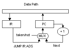
MAR is on the left hand side (being written into), therefore conflict but for a memory chip, we assume the address can be change during the write memory cycle as long as it was hold for a certain time. PC is also having conflict. At Fstage, PC = PC+1 but for JMP instruction, PC = IR:ads. This situation can be remedy by using a multiplexor circuit for writing into PC and PC = IR:ads when the jump is taken (because it jumps and hence not using the next instruction in sequence).
Fstage Xstage
jmp PC=PC+1 PC=IRx:ads

TIMING of S1 (count ifetch as 2 clocks)
load 5
store 5
jmp 3
jal 3 (trap)
mov 4
loadr 5
storer 5
add 4
cmp 3
inc 4
The experiment is carried out to compare s1 and S1-pipe and S1-pipe with register forwarding and S1-pipe with forwarding and delay branch.
inst clocks stall
% CPI speedup P-PF PF-PFD
S1 1110 4642
- -
4.18 - - -
S1-P 1112 3136 2024
64.5 2.82 0.48 - -
S1-PF 1112 1304 202
15.4 1.18 2.54 1.39 -
S1-PFD 1112 1114 2
0.18 1.002 3.17 1.81 0.18
S1-p is faster than S1 48% and S1-pF is faster than S1 254%. S1-PF is
faster than S1-P 139%. The maximum gain is obtained using forwarding.
It reduced stall cycle from 64.5% to 15.4%. By using delay branch this
can be reduced further but the gain is not as much as using forwarding.