This lecture is focus on S2 assembly language. For Rz presentation see this lecture. This lecture explains interrupt extensively and leaves the io ports to be discussed in the next lecture (using Rz).
Using the IOT board as a platform, the input/output ports are defined as follow:
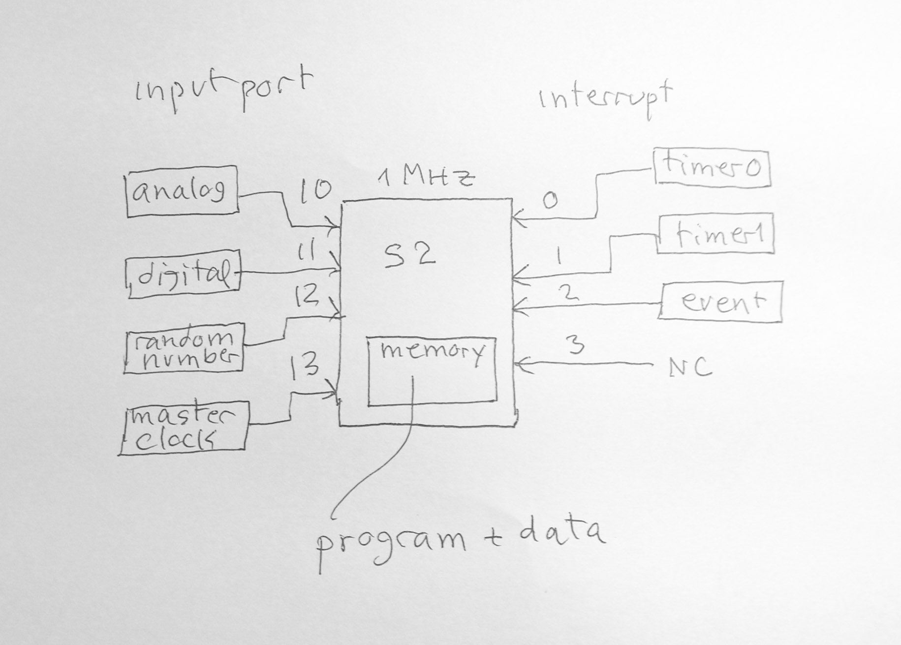
input ports
10 analog wave sine ware period 1000, amplitude 50
11 digital wave square wave period 1000, amplitude 5
12 random number (uniform 100..500)
13 master clock (integer)
interrupt
0 timer0
1 timer1
2 event trigger
3 no connection
trap function
trap r0 #0 stop
trap r1 #1 print int from r1
trap r1 #2 print char from r1
trap r1 #3 print string (array of char, terminate by 0)
trap r1 #4 input string, return address of string
(default at 15000)
trap r0 #13 set timer0
trap r0 #14 set timer1
trap r0 #15 disable interrupt (0,1,2,3)
trap r0 #16 enable interrupt (0,1,2,3)
trap r0 #18 readport (10,11,12,13)
trap r0 #19 malloc
processor s2.1 extended instruction for interrupt
int       xop 23  int r1 (r1 as int
      number), software int

      reti      xop 24  return from int
pushm sp xop 26 push multiple r0..r15 to stackpopm sp xop 27 pop multiple r0..r15
from stackxch r1 xop 28 exchange register r1 with
RetAds swi xop 29 sleep and wait
for interrupt (any int.)An interrupt is an asynchronous event happens outside of a processor. When an interrupt occurs a processor "responses" to it at the end of the current instruction by jumping to the interrupt service routine (ISR) similar to call a subroutine. The return address is saved in a special register (RetAds). At the end of ISR, it returns to continue at the next instruction where the interrupt occurs, using "reti" (return from interrupt) which restore RetAds to PC. S2.1 has "one-level" interrupt, that is, when an ISR is active, it will ignore all other interrupt. S2.1 has four interrupt pins, int0, int1, int2, int3 which int0 has the highest priority. The address of the ISR is stored at M[1000]. It is called interrupt vector. It has to be set before using ISR.
The instruction "int r1" is a software interrupt. When executing this instruction, it behaves just like "int0" occurs. This facilitates the testing of program with interrupt events. It is more useful in multi-core environment when one core can send interrupt to other core.
The instruction "swi" is "sleep and wait for interrupt". It is used to "power down" a processor hence saving the battery. When "swi" is executed, the processor will stop and power down. It waits for an interrupt to occur. When an interrupt occurs, the processor will wake up and the ISR will be activated. After the ISR is completed, it will return to execute the next instruction after "swi".
Here is some example how to write interrupted routines. Let make one process, do the counting of a global variable "cnt". The main program is actually an empty loop but it also terminates the program when the count reach 10. The process is an interrupt service routine (ISR). When an interrupt occurs, ISR is called and executed to the instruction "reti" then it will return to main.
.symbol cnt 100
.code 0
:main

        mov r1 #isr

        st r1 1000   ; set up int vector

        mov r1 #0

        st r1 cnt    ; cnt = 0

      :loop

      ;  this is almost empty loop

        swi          ; wait
      for int

        ld r1 cnt

        eq r2 r1 #10

        jf r2 loop

        trap r0 #0   ; stop


      :isr

      ;  must not use r1

        ld r3 cnt

        add r3 r3 #1

        st r3 cnt

        reti
.end With the default setting in the simulator, the interrupt occurs every 100 instructions. The program will run 1500 cycles before it terminates (one instruction takes one cycle). The interrupt occurs 10 times. Each time, the ISR is executed 4 instructions and the main while loop executes 4 instructions. Totally 80 instructions will be executed before the program ends. Without "swi" the processor will execute all 1500 instructions because it will loop continuously and check the "cnt" to see if it has reached the end.
The next examples show how to run two concurrent processes using interrupt. This is achieved by switch the interrupt vector. Only one interrupt is used. When the first interrupt service routine finished, it switches int vector to the other interrupt service routine. So that the next interrupt activates the second interrupt service routine. Similarly, when the second one is finished, it switches int vector back to the first one.
; using interrupt to run two concurrent processes

        ;    by switching interrupt vector

        ;    one process counts even numbers

        ;    another process counts odd numbers


        .symbol

          cnt1   100

          cnt2   101

          stop   0
.code 0:main mov r1 #count1 st r1 1000 mov r1 #0 ; the first
process starts counting from 0 st r1 cnt1 mov r1 #1 ; the second
process counts from 1 st r1 cnt2 mov r2 #0 ; init i:while swi add r2 r2 #1 ; inc i lt r3 r2 #20 ;
loop 20 times jt r3 while trap r0 #stop; interrupt service routine1
:count1
ld r4 cnt1
trap r4 #1 ; print cnt1
add r4 r4 #2 ; cnt1 += 2
st r4 cnt1
mov r4 #count2 ; switch int vec
st r4 1000
reti
; interrupt service routine2
:count2
ld r4 cnt2
trap r4 #1 ; print
cnt2
add r4 r4 #2 ; cnt2 += 2
st r4 cnt2
mov r4 #count1 ; switch int vec
st r4 1000
reti
.endC:\iot-rz\test>sim21 two-cnt.obj
load program, last address 26
>g
interrupt0
0 interrupt0
1 interrupt0
2 interrupt0
...
18 interrupt0
19 interrupt0
20 stop, clock 3161, execute 239 instructions
>q
:process1

      ....

      ...  <-  int1

      :L1

      ....

      ...  <-  int3


      :process2

      ...

      ...

      ... <- int2

      :L2

      ...
xch r1 xop 28 exchange RetAds with r1p1()
i = 0
while(1)
print i
i = i + 2
p2()
i = 1
while(1)
print i
i = i + 2:PCB
next PCB
r0...r15tswich()
get a handle on current PCB
get current PC
save current context
get a handle on next PCB
restore next context
set PC of next process; task switcher use r3, r4:tswitch
mov r4 r27
; get current PCB
ld r27 @0 r27 ; get next
PCB
xch
r3
; get current process PC
pushm
r4
; save local regs to current PCB
add r27 r27 #16
popm
r27
; restore next PCB
xch
r3
; set current PC, jump to next process
reti
; demo two concurrent processes using a task switcher
.symbol
PCB1 1100
PCB2 1200
.code 0
; set up
mov r1 #tswitch
st r1 1000 ;
set int vec to tswitch()
mov r1 #PCB2
st r1 PCB1
mov r1 #PCB1
st r1 PCB2 ;
set up PCB
mov r1 #p2
mov r2 #PCB2
st r1 @4 r2 ; set
PC of p2
mov r27 #PCB1 ; set current PCB
mov r1 #50
trap r1 #13 ; set
timer0 = 50
jmp
p1
; start p1
:p1
mov r6
#0 ; i = 0
:loop1
trap r6 #1 ;
print i
add r6 r6 #2 ; i += 2
jmp loop1
:p2
mov r6
#1 ; i = 1
:loop2
trap r6 #1 ;
print i
add r6 r6 #2 ; i += 2
jmp loop2
:tswitch

        mov r4 r27
      ;  get current PCB

        ld r27 @0 r27       ;  get next
      PCB

        xch
      r3
      ;  get current process PC

        pushm
      r4
      ;  save local regs to current PCB

        add r27 r27 #16

        popm
      r27
      ;  restore next PCB

        xch
      r3
      ;  set current PC, jump to next process

        reti
.end
tswitch() which then switches between
these two processes. Here is the output from the simulator:C:\iot-rz\test>sim21 tswitch.obj
load program, last address 29
>g
0 2 4 6 8 10 12 14 16 18 20 22 interrupt0
1 3 5 7 9 11 13 15 17 19 21 23 25 27 interrupt0
24 26 28 30 32 34 36 38 40 42 44 46 48 50 interrupt0
29 31 33 35 37 39 41 43 45 47 49 51 53 55 interrupt0
. . .
136 138 140 142 144 146 148 150 152 154 156 158 160 162 interrupt0
141 143 145 147 149 151 153 155 157 159 161 163 165 167 interrupt0