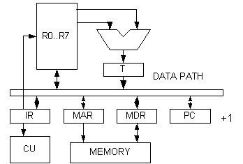

Instruction set design
instruction
op
load M, r 0
M -> r
store r, M 1
r -> M
jump c, ads 2
call 0, ads 3 push(PC),
goto ads
xop
7
mov r1,r2 0
r1 -> r2
load (r1),r2 1 (r1) ->
r2 load indirect
store r1,(r2) 2 r1 -> (r2)
store indirect
add r1,r2 3
r1 + r2 -> r1
cmp r1,r2 4
compare, affect Z,S
inc r1 5
ret
6 pop(PC)
r 0..7
c 0..6 conditional : 0 always, 1 Z, 2 NZ, 3 LT, 4 LE,
5 GE, 6 GT
M/ads 0..1023 address space
Notation
// comment
dest = source // data move from source to destination
e1 ; e2 // event
e1 and e2 occur on the same time
M[a]
// memory at the address a
IR:a
// bit field specified by a of IR
<name>
// macro name
op()
// ALU function
// main loop
repeat
<ifetch>
<decode>
<execute>
<ifetch>
MAR = PC
MDR = M[MAR] // MREAD
IR = MDR ; PC = PC + 1
<load>
MAR = IR:ADS
MDR = M[MAR]
R[IR:R0] = MDR
<store>
MAR = IR:ADS
MDR = R[IR:R0]
M[MAR] = MDR // MWRITE
<loadr>
MAR = R[IR:R1]
MDR = M[MAR]
R[IR:R2] = MDR
<storer>
MDR = R[IR:R2]
MAR = R[IR:R1]
M[MAR] = MDR
<move>
T = R[IR:R1]
R[IR:R2] = T
<add>
T = add(R[IR:R1], R[IR:R2])
R[IR:R1] = T
<compare>
CC = cmp(R[IR:R1], R[IR:R2]) // condition
code set
<increment>
T = inc(R[IR:R1])
R[IR:R1] = T
<jump>
if testCC(IR:R0)
then PC = IR:ADS
<call>
T = add1(R[7])
R[7] = T
MAR = R[7] // sp+1 then put stack
MDR = PC
M[MAR] = MDR
PC = IR:ADS
<return>
MAR = R[7]
MDR = M[MAR] // get stack then sp-1
PC = MDR
T = sub1(R[7])
R[7] = T
// instruction fetch can be faster
<ifetch2>
MAR = PC
IR = MDR = M[MAR]; PC = PC + 1
TIMING of S1 unit clock (count ifetch as 3 clocks)
load
6
store
6
jmp
5
call
9
mov r r 5
load (r) r 6
store r (r) 6
add
5
cmp
4
inc
5
ret
8
Call and return take the longest time in the instruction set. Calling a subroutine can be made faster by inventing a new instruction that does not keep the return address in the stack (and hence the memory) but keeping it in the register instead. Jump and link (JAL) just saves the return address in a specified register and jump to the subroutine. Jump Register (JR) then does the reverse. It does the job of the "return" instruction. The register that stored return address must be saved to the memory (i.e. manage by the programmer) if the call to subroutine can be nested. This will reduce the clock to 5 for "jal" and 4 for "jr". This shows that using registers can be much faster than using the memory.
jal r, ads store PC in r and jump to ads
jr r jump
back to (r)
<jal>
R[IR:R1] = PC
PC = IR:ADS
<jr>
PC = R[IR:R1]
Example of an assembly program for S1. Find sum of an array
: sum a[0] .. a[N]
sum = 0
i = 0
while ( i < N )
sum = sum + a[i]
i = i + 1
.ORG 0
// address code
load ZERO r0
0 0 0 20
store r0 SUM
1 1 0 21
store r0 I
2 1 0 22
load N r1
3 0 1 23
load I r3
4 0 3 22
loop cmp r3 r1
5 7 4 3
jmp GE endwhi
6 2 5 16
load BASE r2
7 0 2 24
add r2 r3
8 7 3 2 3
load (r2) r4
9 7 2 2 4
load SUM r5
10 0 5 21
add r5 r4
11 7 3 5 4
store r5 SUM
12 1 5 21
inc r3
13 7 5 3 0
store r3 I
14 1 3 22
jump loop
15 2 0 5
endwhi load SUM r0 16 0 0 21
call print
17 3 0 1001
call stop
18 3 0 1000
.ORG 20 // data
ZERO 0
20 0
SUM 0
21 0
I 0
22 0
N 100
23 100
BASE 25
24 25
a[..] a[0]
25 a[0]
a[1]
26 a[1]
...
...
S1 runs 1110 instruction with 5963 clocks, CPI = 5.37
An object file has the following format
a ads set
PC to ads
i op r ads instruction
op
i 7 xop r1 r2 instruction xop
w data set
that address to value "data"
t
set trace mode on
d start nbyte dump memory n byte
e
end of object file
Be careful, the input routine is not robust. A malformed input
line can caused unpredictable result. The input loop is limited to
200 words (to prevent infinite loop).