This chapter lays the basic knowledge of the subject. We give an overview and the perspective of computer architecture. We look at architecture from the point of view of a computer designer. We describe the components and the organisation of computer systems in many levels of abstractions. We study the "description of an architecture" which specify a computer system unambiguously. We answer the question "How can a computation is achieved by an architecture". The relationship between architecture and computer languages is important and several issues have been addressed. We discuss the most important aspect of modern computer design: the performance issue. Finally, a brief history of computer is discussed. Computer history itself is a very fascinating subject.
Architecture concerns function
Architecture concerns "function" of the system. Function determines what the system is capable of. The how question is answered by an “implementation” of the system which depends on technology. A computer system consists of many parts. A part can be divided into subparts and forms a hierarchy. Computer architecture concerns how to compose these parts to provide a system that has desired functions under various constraints.
A computer system has a central processing unit (CPU), memory, input/output, interconnections. A CPU consisted of an arithmetic logic unit (ALU), datapath, control unit. The memory subsystem consisted of hierarchical structure: cache memory (high speed memory), main memory, virtual memory. The input/output system consisted of various peripherals such as a visual display unit (VDU), a keyboard, input devices, an interface to the network, various kind of secondary storage, floppy disk, hard disk etc. The interconnections link every parts together, the internal bus, the external bus, I/O channels, ports.
A computer designer must explore many possibilities of choosing and integrating various “components” of a system to satisfy a set of constraints stated in a requirement. A computer designer must make decision how to select and integrate various components such as processor, memory, input/output into a computer system. Computer architecture is driven by the advancement of technology. A designer must evaluate an architecture with its technology. The study of computer architecture is the study of method for selection and evaluation. Computer architecture is different from its implementation. Various parts of a computer can be either hardware or software. Hardware and software are interchangeable depending on technology.
One important aspect of computer design is the instruction set design (or instruction set architecture ISA). A classical view of computer architecture is that the architecture is what the assembly language programmer see, i.e. computer architecture is the instruction set.
A broader view of computer architecture includes the organization of a computer system. An implementation can be regarded as two aspects, one is the organization, and the other is the technology. The organization describes the functional units inside a processor and their relationship. The technology aspect determines how it is possible to build a processor.
A computer system can be seen as many level of descriptions, from the applications to the lowest level of electronic circuits. A computer system consisted of many parts of which can be regarded as "layers". These layers are described at different "level of abstraction". There are many ways to define the level of abstractions. For example, a computer system at the bottom level is consisted of the actual hardware devices: a central processing unit, a memory, input/output devices and interconnections. These hardware devices can be described at the level of: functional units, finite state machines, logic gates down to the electronic circuits. On top of hardware of the system, an operating system gives services to application programs. The interface between programs and hardware is the instruction set description. A computer system can also be viewed as having two aspects: physical and logical. The "physical" system is composed of the actual physical components. The "logical" system describes the design and the organization.
Figure 1.1 the level of description of computer systems
Application level is what a user typically sees a computer system, running his/her application programs. An application is usually written in a computer language which used many system functions provided by the operating system. An operating system is abstraction layers that separate a user program from the underlying system dependent hardware and peripherals.
The level of traditional computer architecture begins at instruction set. An instruction set is what a programmer at the lowest level sees of a processor (programming in an assembly language). In the past, instruction set design is at the very heart of a computer design. The concept of the family of computer promoted by IBM around 1970. They proposed the concept of one instruction set with different level of performance (for the price) for many models. This concept is possible because of the research effort of IBM in using "microprogram" as the method to implement a control unit. However as the present day processor designs converge, their instruction sets become more similar than different. The effort of the designer had turned to other important issues in computer design.
Finite state machine description is a mathematical description of the "behaviour" of the system. It is becoming an important tool for verification of the correct behaviour of the hardware during designing of a processor. As a processor becomes more and more complex, a mathematical tool is required in order to guarantee the correct working behaviour since an exhaustive testing is impossible and partial testing is expensive (but still indispensable). Presently (year 2000) it is estimated that more than half of the cost in developing a processor is spent on verifying that the design works according to its specification.
The lower level of logic gates and electronics describe the logical and actual circuit of a computer system and belongs to the realm of an electrical engineer.
This level of abstraction enables separate layers to be designed and implemented independently. It also provides a high degree of tolerant to changes. A change in one layer has limited effect on other layers. This degree of "decoupling" is important as a computer system is highly changeable and technology dependent. The changes are very frequent; a new microelectronic fabrication process leads to a higher speed device, a new version of operating system provides more functionality, new applications are created. Without separation into layers all these changes will interact in a complex and uncontrollable way. The level of abstraction is a key concept in designing and implementing a complex system.
The basic elements are logic gates. The complete set of gates composed of: AND, OR, NOT gates. (This is not the only basis, there are several others). NAND gate (NOR gate) is complete because it can performed the same function as AND, OR, NOT gates. Logic gates are used to build larger "functional units" which are the building blocks of a computer. There are two types of logic gates, one with memory and one without.
A combinational logic has no memory, output is the function of input only. To create memory, the output is fed back to input. The resulting circuit is called sequential logic.
A sequential logic is the logic gate with memory. The basic element is called flip-flop. There are many types of flip-flop such as RS, JK, T and D-type flip-flop. Sequential circuit has "states". The output depends on both inputs and states. Sequential logic requires clocking. There are two types, synchronous and asynchronous. A synchronous logic has a common clock. It is a rule of thumb for design engineers to use synchronous logic because it is much simpler to design and to debug. One draw back of synchronous design is that the maximum speed of the clock is determined by the slowest part of the circuit. Therefore it is a worst-case design. A asynchronous logic has no central clock, hence it can be much faster than synchronous design when the clock rate is very high and clock skew becomes a problem. The output of one stage is used to drive the next stage. It is difficult to arrange the timing for the circuit to operate properly as the delay of each element affects the timing of the whole circuit. There are large variation of delay when fabricating each logic element. This fact often makes asynchronous design impractical or very expensive.
An example of asynchronous design illustrates the point above. The super computer ILLIAC from the university of Illinois at Urbana-Champaign has asynchronous design to achieve high clock rate. Each connecting wire has to be trimmed manually to properly adjusted the delay time of each module. In the era of VLSI, most design is synchronous because it is much easier to get the design to work properly. Presently due to the advancement of asynchronous design methodology and the promise of very high speed result (and low power consumption) the asynchronous design is coming back. It is an active area of research. There are many standard textbooks on digital logic design which students can explore the subject in much more details such as the one by Katz [KAT93].
In order for a computer to execute a program, many functional units are necessary. Functional units are the building blocks of computers. These building blocks plus the control unit constitute the basic structure of computer. Basic units to perform arithmetic functions are: adder, multiplier, shifter etc. They reside in an ALU. A functional unit may be built on smaller units, for example, in an adder, a Half adder is built out of basic gates and two Half adders combined into a Full adder. The length of operand affects the speed of adder circuit. The delay comes from the need to propagate the carry bits. Carry-look-ahead logic, invented by Charles Babbage [LEE95] who was considered the father of modern computer, is used to speed up the propagation of the carry bits.
Description of an architecture
Charts and block diagrams can be used to illustrate a "structure" of a computer system with blocks denote functional units (or components) and lines as connections or relations between those units. There are many notation systems, PMS-ISP [BEL71] instruction set processor, RTL (Register Transfer Language), even APL like notation for behavioural description by Blaauw and Brooks [BLA97]. We shall discuss the PMS-ISP notation because it is well-known and is used in many historical work in computer architecture, then we will give our version of the descriptive system that is composed of structural chart, instruction set and behavioural description.
PMS and ISP descriptive systems
This descriptive system consisted of two levels of description. The PMS describes more of the total system. The ISP provides the description at the level of the instruction set.
Digital computer can be viewed as discrete state systems that have three characteristics:
There are seven basic component types in PMS: Memory (M), Link (L), Control (K), Switch (S), Transducer (T), Data-operation (D), and Processor (P). An operation is a transformation of bits from one specific memory to another, M to M'.
Computer model in PMS
A configuration of a computer is
C := Mp - Pc - T - X
where Pc indicates a central processor and Mp a primary memory. T is a transducer connected to the external environment, represented by X (input/output devices).
Pc can be decomposed into a control K and an arithmetic unit or data-operation D
Mp - K - T | Ms - X
|
D
where "|" expresss alternatives (T "or" Ms, the secondary memory)
The behaviour of a processor is determined by sequence of its operations. This sequence of operations is determined by a set of bits in Mp, called the program, and a set of interpretation rules that specify how particular bit configurations evoke the operations. ISP (Instruction set processor) provides a scheme to specify any set of operations (instructions) and any rules of interpretation.
An instruction expression has the form:
condition --> action-sequence
The --> is the control action K of evoking an operation. Each action has the form:
memory-expression <-- data-expression
The <-- is the transmit operation of a link (correspond to the assign operation). The left hand side describes the memory location, the right hand side describes the information pattern.
An ISP example of the DEC PDP8
Processor state Pc
AC<0:11> the accumulator
AC is a 12-bit register. Comments are in italics. AC is a register in Pc.
Primary memory state Mp
Mp[0:77778]<0:11>
A primary memory consists of 10000 8 (base 8) words of 12 bits each.
Instruction format
PDP8 instruction format is defined as follows:
op<0:2> := instruction<0:2>
indirect_bit / ib := instruction<3>
page_0_bit / p := instruction<4>
page_address<0:6> := instruction<5:11>
This format can be shown in the diagram:
|
op |
ib |
p |
page_address |
0..2 3 4 5... 11
The width of an instruction is 12 bits.
The instruction set
and (:= op = 0) --> (AC <-- AC ^ M[z] )
This describes the opcode of the instruction "and" is 0 and its action is to AND AC and a memory location z, where z is the effective address.
Instruction interpreter
An instruction is fetched from the memory and then executed. Next, the next instruction is fetched and so on (ignoring the interrupts):
Run --> (instruction <-- M[PC]; PC <-- PC + 1; next fetch
Instruction_execution) execute
A state diagram represents the behaviour of the instruction-interpretation process. The K controls the state transitions according to the information in the instruction.
Microarchitecture and behavioural description
We are interested mostly in the microarchitecture, which concerns the processor. We adopt 3 types of notation to describe architecture:
A structural chart shows the distinct components of a processor and their connections. For example, the CRAY-1 super computer [RUS78] is composed of main memory (up to 4 M 64-bit words), scalar registers S (8 ´ 64-bit), backed by a 64-elelment vector register T, address registers A (8 ´ 24-bit), backed by a 64-element 24-bit vector register B, vector registers V (8 ´ 64-bit), vector units, floating-point units, scalar units, and address units.
Figure 1.2 Structure chart of CRAY-1
An instruction set is expressed by the instruction formats and the instruction names. For example, the instruction set of S1 (hypothetical processor used in this book) has one format called L-format (for long-format), each field is denoted by the fieldname:length.
S1 L-format : op r, ads
| op:3 |
r:3 |
ads:10 |
15..13 12..10 9..0 bit position
Two instructions and their opcodes are: (comments in italics)
0 ld M, r M
-> r load from memory
1 st r, M r
-> M store to memory
A register transfer language is used to describe the step-by-step operation of each instruction. The notation of this RTL is as follows:
Example S1 behavioural description of the "load" instruction
<load>
MAR = IR:ADS
MDR = M[MAR] // memory
read
R[IR:R0] = MDR
The "load" instruction has the opcode = 0. The address (bit ADS of Instruction Register, IR) is read into Memory Address Register (MAR). A memory addressed by MAR is read into Memory Data Register (MDR). The register indexed by IR:R0 is written with the value of MDR. This sequence of operations takes 3 clocks.
How a processor performs computation
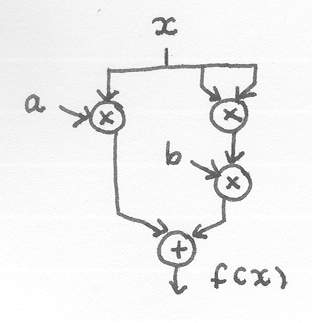
Suppose we want to calculate value of a polynomial
f(x) = a x + b x2
The functional units required to do this computation are multiplier and adder. The desired computation can be performed by directly connect appropriate number of functional units together (Fig graph).
Figure 1.3 a computation graph to evaluate a polynomial
The solution of this computation problem becomes a graph whose nodes are functional units and arcs are connections of data through these units. The computation is performed by the flow of data. In this model every units can be active concurrently. "Programming" in this model becomes specifying the computation graph.
Another way to compute f(x) is by sequentialise the operations (Fig sequential)
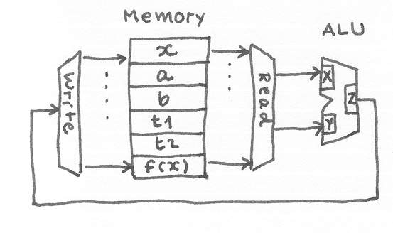
Figure 1.4 a sequential model of computation
The required functional units are memory and a general processing unit. A memory stored all the necessary values: input x, constant a, b, the temporary places to keep intermediate values t1, t2, and the final result f(x). The memory can be read and written to. The memory can be read two values at once and feed the data to a general processing unit, so called Arithmetic Logic Unit (ALU). The processing unit can perform multiplication and addition. It has internal storage to store two input values and one output value. In general, ALU can do a number of computations. Assume its inputs are X, Y, output Z, ALU does Z = f(X,Y) where f = { add, sub, mul, increment, . . .}. The output of the processing unit (Z) is connected to the write port of the memory. Now the desired computation can be performed by executing these steps :
read(x,a)
compute(mul)
write(t1)
read(x,x)
computer(mul)
write(t2)
read(t2,b)
compute(mul)
write(t2)
read(t1,t2)
compute(add)
write(result)
Sequential approach to computation enables functional units to be reused as the computation is performed step-by-step. The intermediate values can be saved in the memory can used in the later steps. The general processing unit can perform a number of different functions such as add, subtract, so that only one unit is sufficient for most kinds of computation. The trade-off is the speed as the computation becomes sequential there is no opportunity for concurrent operations as in the graph model. Sequential machines are highly flexible, use less resource to implement a computation but are slower than the graph machines. However both graph model and sequential model are similar in the sense that the computation is carried out by directing the flow of data through functional units.
The step-by-step instructions of computation in sequential machines become "program". Burks, Goldstein and Von Neumann [BUR46] are the first to propose that programs can reside in the same memory as data. This gives rise to a class of architecture called "Stored program computer" (Fig stored program computer)
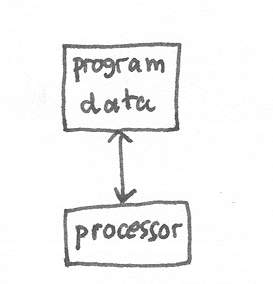
Figure 1.5 Von Neumann architecture
This is the most popular organisation even today. Storing programs and data in the same memory enables a processor to be able to manipulate programs easily. The main disadvantage is the limit of memory bandwidth, which affects the speed of running an application. As the need for more complex applications which required large amount of computation increases, having only one connection between a processor and a memory becomes bottleneck. This phenomenon is called "Von Neumann bottleneck".
Other organisation is possible such as storing programs and data in separate memories (Fig Harvard architecture)
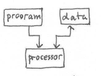
Figure 1.6 Harvard architecture
This organisation is called "Harvard architecture" and is extensively used in the high-speed processor for the purpose for signal processing. This class of processors is called Digital Signal Processor (DSP). DSP has many applications. It is used in modems, in sound synthesizer, in graphic generators etc.
Computer languages and architecture
Programming techniques influence the design of computers since the early day of assembly language programming [HOP97]. Most computers today are implemented as sequential machines. They are suitable to be programmed in a class of high level programming language: procedural languages. The examples of procedural languages are C, Pascal, C++, Java etc. In these languages, the computation is viewed as step-by-step manipulation of values of variables stored in memory.
There are other paradigms of programming. Backus, the father of FORTRAN, gave a lecture is the occasion of his reception of Turing award, titled "Can computers be liberated from Von Neumann bottleneck? " [BAC78]. This lecture advocated a different programming paradigm called Functional Programming. In functional paradigm, programming is viewed as the activity of composing functions. The computation of a function has an important property of "referencial transparency". This means the result of computing a function depends only on its arguments and does not change by where the function resides. This property is contrasted to procedural programming which compute by "side effect", i.e. manipulation of variables depends on states. Functional programming helps to promote the correctness of programs. As this paradigm of programming view computation as composing functions, it maps nicely to the graph model of computation. Many proposals being put forward to build machines those are suitable for this class of programming languages, for example a graph reduction machine [KOO90].
Different programming paradigms lead to different architectures. Logic programming paradigm (Prolog programming language and others) requires architecture capable of inferring facts and rules and ability to backtrack efficiently, for example [VM of Edinburgh Prolog]. Japanese proposed and built various types of these machines in the period of their research on Fifth generation computer. Presently, object-orientated programming paradigm is becoming the dominated paradigm. The object-oriented programming languages (Java, C++, Smalltalk etc.) will benefit from machines whose architecture are suitable to implement them.
This section discusses performance issue. How performance of a computer system is defined and measured. Standard references are used to interpret performance figures. Performance can be used in a relative sense, it is the measurement of one system compares to another system.
The first commercial electronic computer appeared around 1950. The first 25 years the performance improvement came mostly from technology and better computer architectures. Later, the improvement mostly came from the advent of microelectronics. The speed increased 18-35% per year. Technology progresses from vacuum tubes to transistors to integrated circuits. The birth of microprocessor around 1970 [FAG96] has great impact on performance of computers. The growth of performance has been highest for microprocessors. Since 1980 the performance double every two years. For example, around 1980 the first IBM PC appeared. Its CPU was an Intel 8088, a 16-bit CPU with 8 MHz clock. It had 16Kbytes of memory, one floppy disk and no hard disk. The later model offered 5Mbytes hard disk (so called IBM XT). Today (year 2000) a PC is equipped with Pentium 32-bit CPU with 500 MHz clock, 64Mbytes of memory and 10 Gbytes disk. Its performance is around 1000 times of the first PC.
Performance is measured by running "mixed jobs". Therefore it is not an absolute figure. It depends on the kind of jobs that are used to measure the performance. One phenomenon that occurs in the computer technology is that the performance of a processor has been double every 18 months. This observation is proposed by Moore [MOO65], who is the pioneer (among a number of other engineers) of integrated circuit fabrication. He was with Fairchild, one of the earliest IC manufacturer. That observation is known as Moore's law. The main reason that makes this law possible is the rapid advance of the IC manufacturer technique: the shrinking of the physical dimension of the electronic circuits. For the last 30 years semiconductor technology has been roughly quadrupling every three years. This gives an exponential base of about 1.59 instead of the base 2 proposed in Moore’s original paper. A more accurate formula for Moore’s law is:
N device on chip = 1.59 (year – 1959)
We define performance as:
Performance = how fast a processor complete its job.
Performance is measured by its execution time of a suite of programs called "benchmark programs". The execution time depends on three factors.
execution time = number of instruction used ´ cycle per instruction ´ cycle time
These factors depend on various designs:
The performance can also be measured by response time and throughput. The response time is the time between the starting of a user job and the time when the computer replies. Under multiple jobs, a better measurement is the throughput. Throughput measures how many jobs can be completed in a unit time. The response time is called latency of a system. The throughput is also called the bandwidth of a system.
Performance = how fast a computer can run
performance = response time ( latency)
performance = throughput (bandwidth)
The fastest machine of the year 1997 is the ASCI-Red of the department of energy, USA. It is composed of 2048 nodes of Pentium Pro with collective memory of 600 G bytes. Its peak performance is 1.8 Tflops and it has run 630 Gflops on 3400 nodes (running simulation of motion of particles) [KAR98].
To compare the performance of two machines, it is natural to state "X is n% faster than Y". The ratio of the execution time is used to state how much one machine is faster than the other machine. The performance is the inverse of the execution time. The following relationships can be derived:
X is n% faster than Y
execution time Y / execution time X = 1 + n/100
performance = 1/ execution time (or 1/t)
execution time Y / execution time X = performance X / performance Y
n = (performance X - performance Y) / performance Y
The performance improvement can be measured in term of “speedup”. With the advent of speed enhancement design such as pipeline and parallelism, Amdalh's law [AMD67] states how much performance improvement can be achieved for a given task using the enhancement. The speedup is defined as follows.
speedup = P e / P
speedup = T / T e
where P e is performance with enhancement use, P is performance without enhancement use, T e is execution time with enhancement use, T is execution time without enhancement use.
If enhancement is used only partially the speedup will be severely limited. Let f be the fraction that enhancement is used.
execution time new = execution time old ( (1 - f) + f / speedup)
speedup overall = 1 / ((1 - f) + f / speedup )
Therefore the limit depends on how much the enhancement has been used. In achieving speedup by parallelization, Amdalh's law predicts that speedup will be limited by the sequential part of the program. Let see some numerical example.
Example: A computer has an enhancement with 10 times speedup. That enhancement is used only 40% of the time. What is the overall speedup?
speedup overall = 1/ ((1 - 0.4) + 0.4/10 ) = 1.56
Please note that Amdalh's law applies only with the problem of fixed size. When problem size much larger than the machine, Amdalh's law doesn't applied. This is why the massively parallel machine is still possible.
In order to understand the effect of different instruction set, understanding of assembly language is required. An example of assembly language programming is illustrated as follows.
Suppose a hypothetical machine has the typical instruction set composed of {load, store, compare, increment, jump condition}. It has an index register (x) and a set of general purpose register (r0..r7).
Find max of array[i], i=1..N
max = array[1]
i = 2
while i <= N
if max < array[i] then max = array[i]
i = i + 1
end
let the array[i] be accessed by load r0,array,x
max
equ $100
array equ $200
load x, #1
load r0, array ; x
store r0, max ; max = array[1]
load x, #2 ; x keeps i
loop: cmp x, #N
jump GT exit ; i <= N
load r0, max
load r1, array ; x
cmp r0, r1 ; max <
array[i]
jump GE skip
store r1, max
skip: inc x
jump loop
exit: END
We count the number of instruction being executed to calculate CPI.
let N=3, array[ ] = 1,2,3
|
frequency |
clock |
|
|
load |
3+4 |
2 |
|
store |
1+2 |
2 |
|
cmp |
4 |
1 |
|
jump |
4 |
2 |
|
inc |
3 |
1 |
Total 21 instructions, 35 clocks. CPI = 35/21 = 1.67
The history of computer is full of interesting episodes. We will to start off with asking the question "Who made the first computer?" To find out the answer we need to clarify some definition. What kind of machine is considered to be a "computer"?
In mechanical era, the computing machine is really a mechanical calculator. In 1890, Charles Babbage designed and attempted to build Analytical Engine, which contained many ideas that are used in modern computers such as Arithmetic Logic Unit. However, it was never finished as the British government finally stopped funding for the construction of Babbage's Analytical Engine.
The MARK 1 (also known as the IBM automatic sequence controlled calculator) developed in 1944 at Harvard University by Howard Aiken with the assistance of Grace Hopper. It was used, by the US Navy, for gunnery and ballistic calculations, and kept in operation until 1959. The computer was controlled by pre-punched paper tape and could carry out addition, subtraction, multiplication, division and reference to previous results. Numbers were stored and counted mechanically using 3000 decimal storage wheels. It was electro-mechanical computer and was slow requiring 3-5 seconds for a multiplication operation. This machine is a "configurable calculator", in an essence it is an implementation of Babbage's machine with newer technology.
When does a machine become a computer? We will define a modern computer as a general purpose programmable machine. The "programmability" is considered an essential characteristic of a computer. Alan Turing was the genius who proved that the general purpose computer was possible and simple in 1937 in his seminal paper "On computable numbers" [TUR37]. To have this programmability a computer must have the "stored program".
Figure the ABC diagram [IOW99]
The ABC (Atanasoff Berry Computer) was built in 1937-1942 at Iowa State University by John V. Atanasoff and Clifford Berry [BUR88] [MOL88]. It introduced the ideas of binary arithmetic, regenerative memory, and logic circuits. This machine was essentially a powerful configurable calculator. Mauchly spent many days with Atanasoff in 1940 studying this machine. This was the first computer to use electronic valves (tubes) to perform arithmetic. Atanasoff stopped developing this with the advent of war, and never returned to it. This machine doesn't have the "stored program" ability.
In 1943 Flowers in Bletchley Park built the first Colossus machine, a programmable computer specially designed to crack the German Enigma military cypher machines. It is not a "general purpose" and has no "stored program". In 1944 Zuse in Germany started work on a truly general purpose programmable computer of modern type, known as the Z4. The end of the war interrupted development. Zuse's earlier machines (Z1-Z3) were elegant and sophisticated in design, for example using the much more economical binary representation of numbers, but were basically modernised Babbage machines.
A group of scientists and engineers at the University of Pennsylvania's Moore School of Electrical Engineering built ENIAC (Electronic Numerical Integrator and Computer) in 1946 [BUR81]. It was programmed by a plug board, which wired up the different calculation units in the right configuration, to evaluate a particular polynomial. Eckert and Mauchly, the designers, at this time patented a digital computing device, and are often claimed to be the inventors of the first computer. It was later proven in a 1973 US court battle between Honeywell and Sperry Rand that while spending five days at Atanastoff's lab, Mauchly observed the ABC and read its 35-page manual. Later it was proven that Mauchly had used this information in constructing the ENIAC. Therefore, John Vincent Atanasoff is now (by some US historians) heralded as the inventor of the first electronic computer.
In 1945 John Von Neumann published the EDVAC report, a review of the design of the ENIAC, and a proposal for the design of EDVAC. This is widely regarded as the origin of the idea of the modern computer, containing the crucial idea of the stored program. A processor fetches instructions from memory. It also read and write data to and from memory. This is called "Von Neumann" architecture where data and instruction co-resides in a memory. This idea came from the proposal of an electronic computer by US Army Ordnance in 1946. Surprisingly, Von Neumann himself is not the first author of that proposal [BUR46]. However, Von Neumann name is honored because of his contribution to the development of this type of computer which has now becomes ubiquitous. The implementation of this design was completed in 1952.
In 1946 The National Physical Laboratory appointed Turing, who had been developing ideas of implementing his Turing Machine concept of general purpose computation in electronic form, to a rival British project intended to outclass EDVAC, known as the ACE. ACE design was at the time the most advanced and most detailed computer design in existence. Its construction was completed in 1950 and named the Pilot ACE.
On 21st June 1948 the first stored program ran on the Small-Scale Experimental Machine (SSEM), nicknamed "Baby", the precursor of the Manchester Mk 1 [LAV80]. So Manchester machine was the first to work.
The first program was written by Tom Kilburn. It was a program to find the highest proper factor of any number a. This was done by trying every integer b from a- 1 downward until one was found that divided exactly into a. The necessary divisions were done not by long division but by repeated subtraction of b (because the "Baby" only had a hardware subtractor).
Figure the first program [MAN98]
Trying the program on 218; here around 130,000 numbers were tested, which took about 2.1 million instructions and involved 3.5 million store accesses. The correct answer was obtained in a 52 minute run.
By April 1949 the Manchester Mark 1 had been finished and was generally available for scientific computation in the University. With the integration of a high speed magnetic drum by the autumn, this was the first machine with a fast electronic and magnetic two-level store (i.e. the capability for virtual memory).
In 1951 the UNIVAC 1 commercial computer was produced in US, based on the EDVAC design, and made by Eckert and Mauchly, who by this time had sold their UNIVAC company to Remington Rand. It employed decimal arithmetic.
We will stop our trip to the history of computer here. To find out more, there is a wonderful journal devoted to all aspects of history of computing, "Annals of the History of Computing", IEEE Computer Society.
Time line of the history of computer
1642 Blaise Pascal invented a machine that can add/subtract numbers
1666 Samuel Morland invented a machine that can multiply by repeated addition.
1671 Gottfried Leibniz, an adding and multiplying machine
1820 Charles Babbage, Difference engine
1830 Charles Babbage, Analytical engine (Father of modern computer)
Electro-mechanical era (relays)
1880 Herman Hollerith, punch card machine
1924 Thomas J. Watson founded IBM
1930 Beginning of computer age
Howard H. Aiken, Harvard university (MARK I)
John V. Anatasoff, Iowa State univ.
George R. Stibitz, Bell telephone lab.
Konrad Zuse, Technische Hochschule in Berlin, ZUSE 1
1943 Flowers, Colossus
1946 Eckert & Mauchly, ENIAC
1948 Manchester SSEM
1949 Manchester Mark I
1950 John Von Neumann, EDVAC
1950 Alan Turing, ACE
1951 Forrester (MIT), Whirlwind
1952 Goldstine and Neumann, IAS
1951 Remington Rand, UNIVAC
1952 IBM 701
[AMD67] Amdahl, G., “Validity of the single processor approach to achieving large scale computing capabilities”, AFIPS Conf. Proc., April 1967, pp. 483-485.
[BAC78] Backus, J. "Can programming be liberated from the von Neumann style? A functional style and its algebra of programs", Communications of the ACM, August 1978, 20(8):613-641.
[BEL71] Bell, G. and Newell, A. "Computer structures: readings and examples", McGraw-Hill, 1971.
[BLA97] Blaauw, G., and Brooks, F., Computer Architecture: Concepts and Evolution Addison-Wesley Pub Co., 1997.
[BUR46] Burks, A. W., Goldstein, H. H. and von Neumann, "Preliminary discussion of the logical design of an electronic computing instrument", US Army Ordnance Department Report 1946.
[BUR88] Burks, A., and Burks, A., The First Electronic Computer: The Atanasoff Story, the University of Michigan Press, Ann Arbor, Michigan, 1988.
[BUR81] Burks, A., and Burks, A., The ENIAC: First General Purpose Electronic Computer, The University of Michigan Press, Ann Arbor, Michigan, 1981.
[FAG96] Faggin, F., Hoff, M., Mazor, S., and Shima, M., "The history of 4004", IEEE Micro, December, 1996, pp.10-20.
[GOL47] Goldstein, H., von Neumann, J., and Burks, A., "Report on the mathematical and logical aspects of an electronic computing instrument", Institute of advanced study, 1947.
[ILI82] Iliffe, J., Advanced computer design, Prentice-Hall, London, 1982.
[IOW99] Iowa State University, Department of computer science, http:// www.cs.iastate.edu/ jva/ jva-archive.shtml
[KAR98] Karp, H., Lusk, E., and Bailey, D., "1997 Gordon Bell prize winners", Computer, January, 1998, pp.86-92.
[KAT93] Katz, R., Contemporary Logic Design, Addison-Wesley Pub Co., 1993.
[KOO90] Koopman, P., An Architecture for Combinator Graph Reduction, Academic Press, 1990.
[KUC78] Kuck, D., "The structure of computers and computations", Vol 1, John Wiley & Sons, 1978.
[LAV80] Lavington, S., Early British Computers, Manchester University Press, 1980.
[LEE95] Lee, J., Computer Pioneers, IEEE CS Press, Los Alamitos, California, 1995.
[MAN98] Manchester university, computer science department, MARK1, http:// www.computer50.org/ mark1/ firstprog.html
[MOL88] Mollenhoff, C., Atanasoff: Forgotten Father of the Computer, ISU Press, 1988.
[RUS78] Russell, R., "The CRAY-1 computer system", CACM 21(1), 63-72. January 1978.
[STE88] Steenkiste, P., Hennessy, J., “Lisp on a reduced-instruction-set computer: characterization and optimization”, Computer, vol.21, no. 7, July 1988, pp.34-45.
[TUR37] Turing, A., "On Computable Numbers, with an application to the Entscheidungsproblem", Proc. Lond. Math. Soc. (2) 42 pp 230-265 (1936-7); correction ibid. 43, pp 544-546 (1937).
[FIF] Japanese Fifth generation computer
[PRO] VM of Edinburgh Prolog