We will show how interrupt works. We will program (in a high level
language) the interrupt. We use the simulated IoT (Internet of
Things) board to show how to program a small device. The
software to run all the demo is here
iot-rz-19.zip
platform: IoT board simulator
explain
IoT board
First, let us show a simple example that use interrupt to do the work. We
show how to run a clock using interrupt. This is the program (in
Rz). "clock" is a global variable. int0 is a special subroutine (called
Interrupt Service Routine). In this example, main() does not do
anything. It spends all the time running "while(1) doze()".
doze() puts processor to sleep and waits for the interrutp to occur.
clock


        int0()

          clock = clock + 1

          print(clock)


        main()

          clock = 0

          while(1)

            doze()
In the IoT board, the default setting of the IoT simulator is to run for
10,000 clocks. There are two interrupts already wired to two timers. The
interrupt0 is enable and the timer0 is 150 (clocks).
To understand the above program we need to know how interrupt work. A CPU is interrupted when an external signal triggerred it. Once CPU recognised the interrupt, it completes the current instruction then jump to "interrupt service routine" (ISR for short). ISR performs some task. When it finishes, it "reti" (return from interrupt).
See what is the assembly code of the above program
:int0     ; Interrupt Service Routine

        ...

          ld r1 clock

          add r2 r1 #1

          st r2 clock

        ...

        reti       ;  return from interrupt


        :main

        ...

          mov r1 #0

          st r1 clock

          jmp L103

        :L104

          swi        ;
        <<<<<<<  sleep and wait for int

        :L103

          mov r1 #1

          jt r1 L104

        ...

          ret rads
You probably notice that call ISR is similar to call to a subroutine with
"jal r2 ads" and return from subroutine by "ret r2".
However, "jal" occurs by software but "call ISR" is done by hardware
(external signal)
If we put a periodic clock to the interrupt pin, then the interrupt can
occurs periodically (for example every 20 ms) without software
intervention. This is how the IoT board is wired.
We must set the "interrupt vector" which is the address of the ISR.
In IoT platform it is at M[1000].
Observe the first line in main
:main

        ...

          mov r1 #int0     ; ***** store &int0 to
        M[1000]

          st r1 1000

          mov r1 #0

          st r1 clock

          jmp L103

        ...
on IoT platform we have two interrupts, int0 and int1. Let us demo them
num

        letter


        int0()

          print(num)

          num = num + 1


        int1()

          printc(letter)

          letter = letter + 1
main() settimer0(400) settimer1(431) ei(1) num = 1 letter = 65
while(1)
doze()The next example shows a more "realistic" multitask program. We can do "foreground/background" multitask using "main" to run a continuous task and "int0" to run a periodic (or other intermittent) task. This is usually called "foreground/backgroud".
main() will run "background"
int0() will run "foreground"
We do not use "doze" in main. Here is the program
num

        char


        int0()

           print(num)

           num = num + 1


        delay()

          i = 0

          while(i < 10)

             i = i + 1


        main()

          settimer0(400)

          num = 1

          char = 65

          while(1)

            printc(char)

            char = char + 1

            if(char > 90) char = 65

            delay()
The main program prints a continuous stream to characters ABC...ZA...Z....
and from time to time int0() prints 1, 2, 3 .... . The routine
delay() is run to slow down the main program so that you can see the
output on the screen clearly. Assume this program file named
"multi.txt". Here is what you see on your screen when compile,
assembly, and run this program.
C:\iot-rz\example> rz36 multi.txt > out.txt

      C:\iot-rz\example> as21 out.txt

      C:\iot-rz\example>sim21 out.obj

      >g

      ABCDEFGHinterrupt0

      1 IJKLMNOinterrupt0

      2 PQRSTUVinterrupt0

      3 WXYZABCinterrupt0

      ...

      20 NOPQRSTinterrupt0

      21 UVWXYZAinterrupt0

      22 BCDEFGHIinterrupt0

      23 JKLMNOPinterrupt0
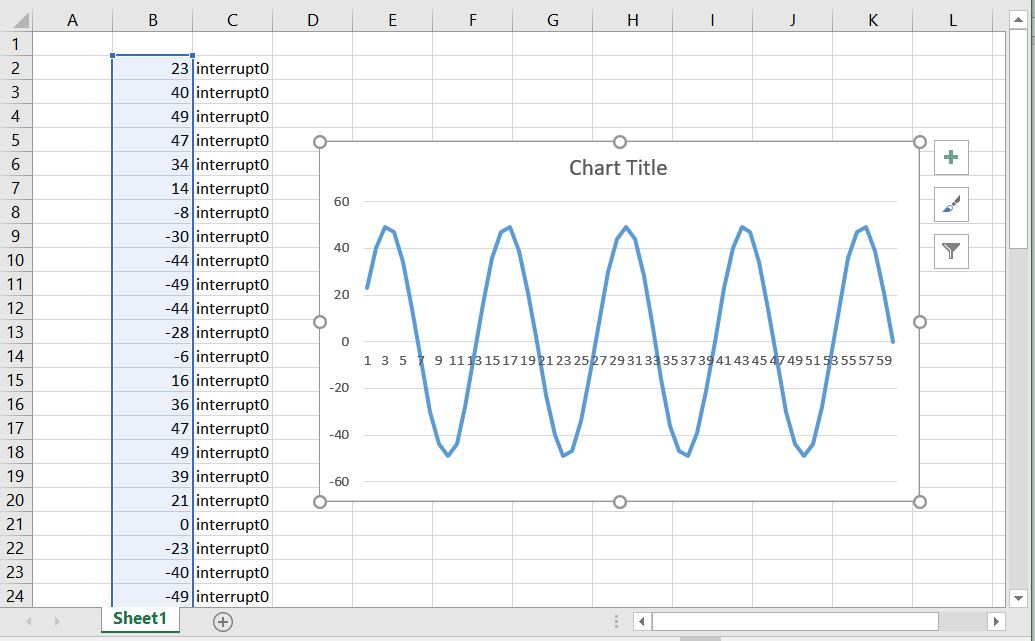
24 QRSTUVWinterrupt0 The final program will do some graphics! IoT board
contains an input port 10 that is connected to a wave generator (sine
wave). We can read the port using int0(). This is called
"sampling". The value is the amplitude of a sine wave.
This is the program, read sine wave.
int0()

          x = readport(10)

          print(x)


        main()

          while(1)

            doze()
Here is the output from the screen
C:\iot-rz\example>rz36 rdsin.txt > out.txt

      C:\iot-rz\example>as21 out.txt

      C:\iot-rz\example>sim21 out.obj

      >g

      ...

      47 interrupt0

      34 interrupt0

      14 interrupt0

      -8 interrupt0

      -30 interrupt0

      -44 interrupt0

      -49 interrupt0

      -44 interrupt0

      -28 interrupt0

      -6 interrupt0

      16 interrupt0

      ...

      36 interrupt0

      47 interrupt0

      49 interrupt0

      39 interrupt0

      21 interrupt0

      0 interrupt0

      -23 interrupt0

      -40 interrupt0

      -49 interrupt0

      -47 interrupt0

      -34 interrupt0