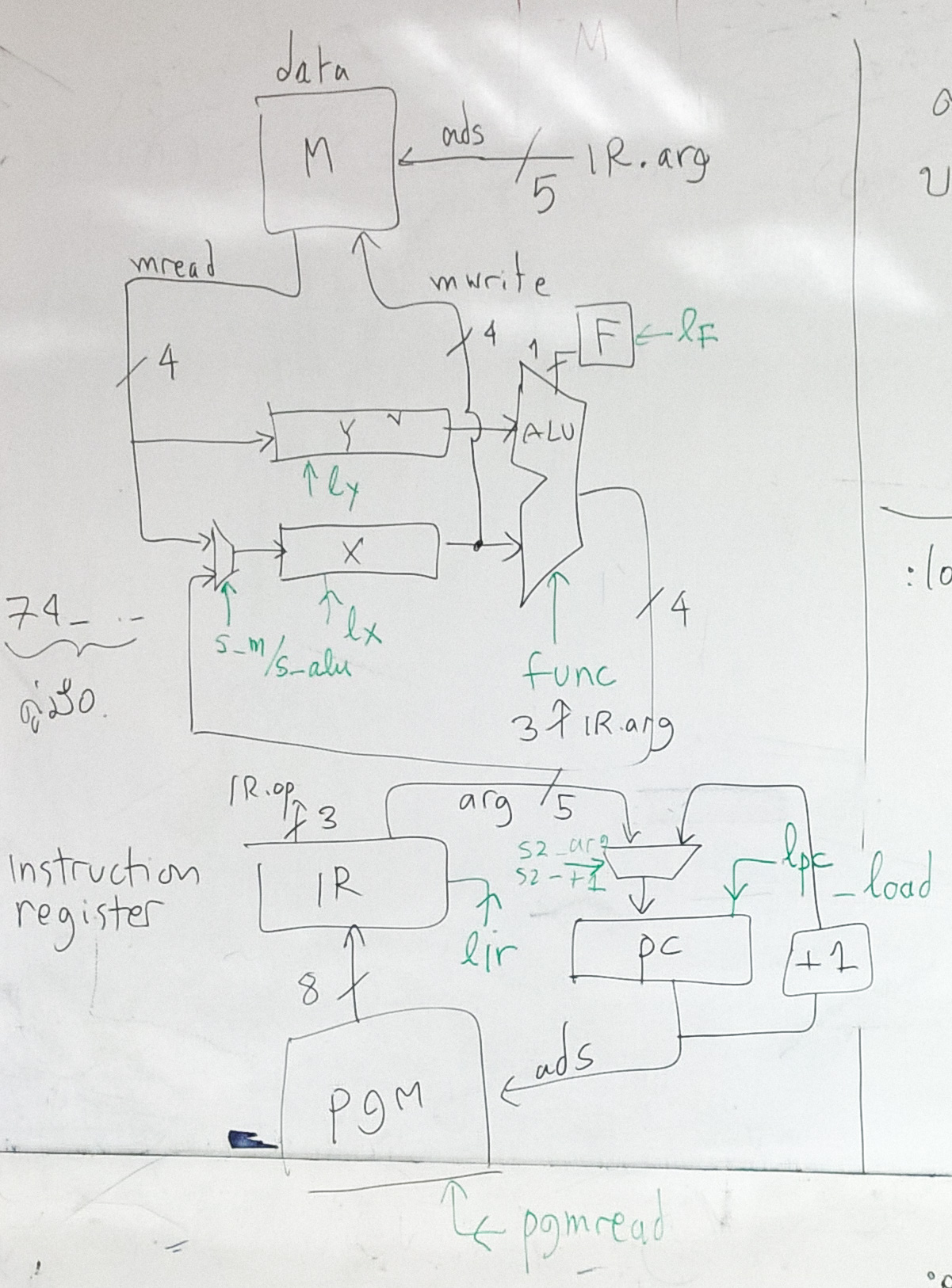
We want to associate the action of datapath with control signals. In
this simulation, the assertion (active) of control signals is explicitly
show in the simulation code.
Each block (such as multiplexor, registers) will have its own module that
associate its output wire with its control signals.
In addition to control signals, we need "wires" to store the value of
functional block.
Notation
to make code easier to read, we will use color to distinguish different
types of signals. Functional block is black, control
signals are green. Wires are red.

We will show the pseudo code of this simulation executing fetch
instruction and execute "add" instruction.
The instruction behaviour is shown first. To execute "add", these steps
occur:
---------------------
// fetch instruction
IR = PGM[PC]

        PC++
// decode
op = irop()   // decode opcode (first 3 bits)

        arg = irarg() // decode arg (last 5 bits)
// execute
switch op

        case xop      //  op == 7 extend opcode

          switch xop

          case 1:  x = x + y   // instruction "add"
----------------------
Now we will add control signals related to these steps. (the green
line in 4B diagram)
fetch instruction involves PC, pc_mux, IR, PGM[]
control signals: pgm_read, lpc, lir
// load pc, load ir
we need to define wire of the output of functional unit
wires
output of pc_mux: pc_mux_out*
output of PGM[]: pgm_out*
here are the definition of functional units
pgm_mem()

          if pgm_read == 1

            pgm_out* = PGM[PC]pc_mux()

          if s_pc_mux == 0

            pc_mux_out* =
        irarg()   // ir last 5 bits

          else

            pc_mux_out* = PC +
        1    // next PC


        pc_update()

          if lpc == 1

            PC = pc_mux_out*


        ir_update()

          if lir == 1

            IR = pgm_out*
Here is the simulation steps
In the beginning all control signals are inactive (0)
// fetch instruction
pgm_read = 1

        pgm_mem()

        lir = 1

        ir_update()
// increment PC
s_pc_mux = 1

        pc_mux()

        lpc = 1

        pc_update()
Now we can decode and execute the instruction in IR
Functional units involve ALU are: ALU, r_mux, x, y.
control signals: func, s_reg_mux, lx
wires
output of ALU: alu_out*
output of r_mux: r_mux_out*
functional units
alu()

          switch func:

          case 1:

             alu_out* = x
        + y

          ...
r_mux()

          if s_reg_mux == 0

             r_mux_out* =
          data_out*

          else

             r_mux_out* =
          alu_out*
x_update()

          if lx == 1

             x = r_mux_out*
here is the simulation step
// execute the instruction in IR
op* = irop()   // get
        first 3 bits of IR

        arg* = irarg() // get last 5 bits of IR


        switch op

        case 7        // extended op

          func =
        decode_arg()   // map arg to func

          switch func

          case 1:     // instruction add

            alu()

            s_r_mux = 1

            r_mux()

            lx = 1

            x_update()
------------------------
Please note that this simulation shows when the control signals are
asserted. It does not show how to generate these signals.
Running the benchmark program with this control signal simulation should
achieve the same result as running the instruction level simulation.
last update 7 Oct 2021