In this tutorial I use ESP32-C3 but it is applicable to ESP32-xx. I install it on Windows 11.
1. Install Arduino IDE
Ensure you have the latest version of the Arduino IDE installed on your
computer.
https://docs.arduino.cc/software/ide/
2. Add ESP32 Board Support
Because the ESP32-C3 is not included in the standard Arduino installation,
you must add it manually:
Open Preferences: Go to File > Preferences (Windows/Linux) or Arduino
> Settings (macOS).
Add URL: In the "Additional Board Manager URLs" field, paste the official
Espressif Arduino-ESP32 URL:
https://espressif.github.io/arduino-esp32/package_esp32_index.json.
Install Package: Go to Tools > Board > Boards Manager, search for
"esp32", and click Install for the package by "Espressif Systems".
3. Select Your Board and Port
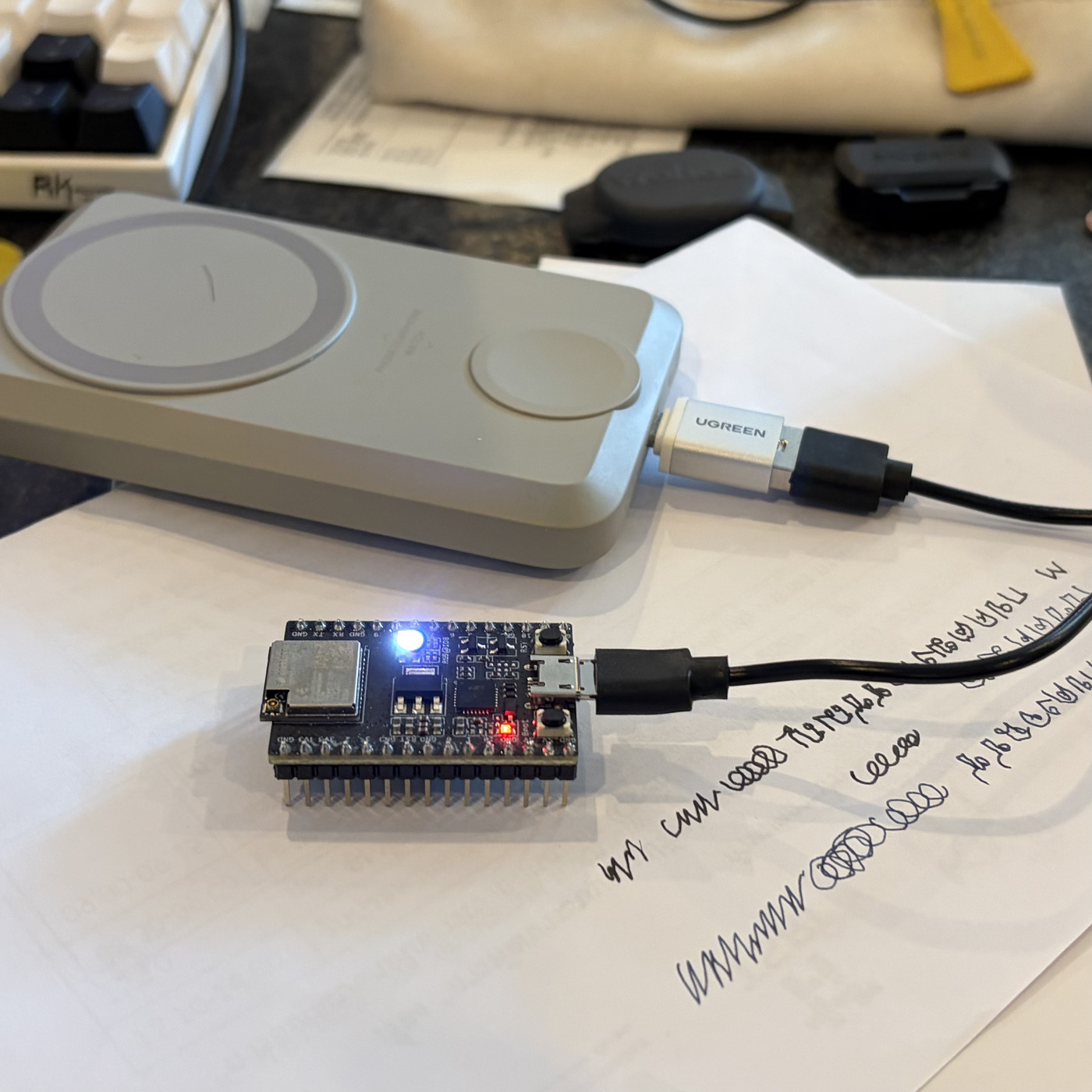
Connect your ESP32-C3 to your computer using a USB data cable.
Board Selection: Go to Tools > Board > esp32 and select ESP32C3 Dev
Module.
Port Selection: Go to Tools > Port and select the COM port (Windows) or
/dev/cu.usbserial (macOS/Linux) associated with your board.
4. Critical Hardware Settings
For the ESP32-C3 to function correctly with the Serial Monitor and for
standard uploads, adjust these settings in the Tools menu:
USB CDC On Boot: Set to Enabled.
This is essential for the ESP32-C3 to output serial data to your computer
over its native USB port.
Upload Speed: Usually 115200 or higher.
Flash Mode: Typically DIO or QIO.
5. Uploading Your First Sketch
You can test the setup using the built-in "Blink" example:
Go to File > Examples > 01.Basics > Blink.
Click the Upload (arrow) button.
Bootloader Mode: If the upload fails with a "Connecting..." error, hold
the BOOT button on the board, press and release the RESET button, then
release the BOOT button to enter programming mode.
Once "Done uploading" appears, press the RESET button on the board to
start the program.
Built-in LED: Most ESP32-C3 boards use GPIO 8 or GPIO 10 for the onboard
LED.
I2C Pins: Typically SDA is GPIO 8 and SCL is GPIO 9.
I find out that it requires "CP210x USB to UART Bridge VCP Driver" because the board in connect to USB port on your computer and it is seen as some device on Ports (COM & LPT) in Windows device manager. This driver will recognise this board as a device on a usual USB port on any modern computer.
The ESP32-C3-DEVKITM-1 on Windows 11 generally requires the CP210x USB to UART Bridge VCP Driver. Download and install the driver from the Silicon Labs website. After installation, the board should appear in Device Manager under Ports (COM & LPT) when connected.
https://www.silabs.com/software-and-tools/usb-to-uart-bridge-vcp-drivers?tab=downloads
I grab the latest one CP210x Universal Windows Driver v 11.5.0
You unzip the file, get into the directory and click "silabser.inf" to install the driver.
You can test the setup using the built-in "Blink" example:
Go to File > Examples > 01.Basics > Blink.
Click the Upload (arrow) button.
Here is the code:
click "->" upload on IDE. It will compile and download to the board.
If successful, this message will come up.
Sketch uses 292522 bytes (22%) of program storage space. Maximum is
        1310720 bytes.

        Global variables use 14344 bytes (4%) of dynamic memory, leaving 313336
        bytes for local variables. Maximum is 327680 bytes.

        esptool v5.1.0

        Serial port COM3:

        Connecting....

        Connected to ESP32-C3 on COM3:

        Chip type:
        ESP32-C3 (QFN32) (revision v0.3)

        Features:
        Wi-Fi, BT 5 (LE), Single Core, 160MHz, Embedded Flash 4MB (XMC)

        Crystal frequency:  40MHz

        MAC:
        84:f7:03:67:23:98


        Uploading stub flasher...

        Running stub flasher...

        Stub flasher running.


        Configuring flash size...

        Flash will be erased from 0x00000000 to 0x00004fff...

        Flash will be erased from 0x00008000 to 0x00008fff...

        Flash will be erased from 0x0000e000 to 0x0000ffff...

        Flash will be erased from 0x00010000 to 0x00057fff...

        Compressed 19520 bytes to 12719...


        Writing at 0x00000000
        [
        ]   0.0% 0/12719 bytes...


        Writing at 0x00004c40 [==============================] 100.0%
        12719/12719 bytes...

        Wrote 19520 bytes (12719 compressed) at 0x00000000 in 1.5 seconds (106.5
        kbit/s).

        Hash of data verified.

        Compressed 3072 bytes to 146...


        . . .

        Writing at 0x00010000
        [
        ]   0.0% 0/162687 bytes...

        Writing at 0x0001bc59
        [==>
        ]  10.1% 16384/162687 bytes...

        Writing at 0x000243d7
        [=====>
        ]  20.1% 32768/162687 bytes...

        . . .

        Writing at 0x00051cb7 [==========================>
        ]  90.6% 147456/162687 bytes...

        Writing at 0x00057740 [==============================] 100.0%
        162687/162687 bytes...

        Wrote 292672 bytes (162687 compressed) at 0x00010000 in 14.8 seconds
        (158.6 kbit/s).

        Hash of data verified.
Hard resetting via RTS pin...
Now you can push RTS button on the board.
The program "blink" is flashed into the board. The board can be disconnected from computer. It still needs power to operate. You can connect the board to a batter pack. Reset and the blink will run.
last update 6 Apr 2026