Pipeline
Principle
Speedup
Stall
* Structural hazard
* Data hazard
* Control hazard
Pipeline performance
Managing pipeline
* Register forwarding
* Branch prediction
* Delay branch
S1 pipeline
The principle of pipeline is to overlap
the operation of various functional units therefore reduce their idle time.
Pipeline is one of the very first technique to increase the performance
invented since the early days of computer. Consider one important
cycle in the working of a processor: executing an instruction. Assume
the cycle is broken into 5 stages :
loop
1 instruction fetch
IF
2 instruction decode ID
3 operand fetch
OF
4 execute
EX
5 write back
WB
A processor executes three instructions : i1, i2, i3
horizontal axis is time, if each stage takes 1 unit time (it is not necessary
that each stage takes equal time but for simplicity) total time is
15 units. If we arrange such that three instructions can be overlapped
:
i1 12345
i2 12345
i3 12345
now the total time is just 7 units. At any time, each stage works on different
instructions, which can be viewed like this after 3 clocks :
Speedup
In an ideal case, the pipeline always be fully used (the number of instruction
is large) hence the speedup is
execution time without pipe / execution
time with pipe
execution time with pipe = execution
time without pipe/ no. of stage in pipe
speedup = no. of stage in pipe
How a pipeline is implemented?
Each stage composed of a functional unit follows by a latch. All
latches are synchronised.
(F = functional unit, L = latch)
in -F-L-F-L- out
clk__|___|
As we have seen the number of stage determine the speedup. What is the
limit of the number of stage? When a task is divided into several
stages which enable overlap operations total time for executing tasks can
be shorten but the delay (setting time of latch) of each stage remains
constant. This delay time is the limit of speedup. Therefore
for a pipeline the latch circuits must be very fast.
Amdahl's law can explain this limit.
Stall of pipeline
A pipeline is not always be filled. When the flow of pipeline is
interrupted, all stages before interruption are stopped (locked), called
stall. The rest of the pipeline can continue to function. There
are three caused
1 structural hazard
2 data hazard
3 control hazard
Structural hazard
caused by two stages of a pipeline accessing the same functional unit.
Because the required resource is busy the pipeline must be stalled.
(more about this in the section pipeline floating point unit)
Data hazard
caused by dependency of data in a sequence of instructions.
i1 R1 = R2 + R3
i2 R4 = R1 + R5
R1 in i1 must be updated before R1 in i2 is read. Because of overlapping
operation, R1 in i1 is updated at WB stage but R1 in i2 is read in OF stage.
x
i1 1 2 3 4 5
x
i2 1 2 3 4 5
Hence the pipeline must be stalled (i2 wait) until R1 is updated (in i1).
The above situation is called Read After Write (RAW) hazard.
Other possibilities are :
- Read after Read (RAR) this doesn't caused hazard
- Write after Read (WAR)
i1 R1 = R2 + R3
i2 R2 = R4 + R5
R2 has WAR.
x
i1 1 2 3 4 5
x
i2 1 2 3 4 5
Because WB is at the later stage than OF in this design, there is no WAR
hazard.
- Write after Write (WAW)
i1 R1 = R2 + R3
i2 R1 = R4 + R5
if R1 in i2 is updated before R1 in i1, the result will be in the wrong
order. This hazard is presented in pipelines that write in more than
one pipe stage (or allow an instruction to proceed even when a previous
instruction is stalled).
Control hazard
caused by transfer of control (jump). The pipeline must be flushed
and start fetching the designated instruction (i*). Therefore stalled
three clocks (or wasted three instructions that already be in the pipeline).
x
i1 1 2 3 4 5
i2 1 2 3 4 5
i3 1 2 3 4 5
i4 1 2 3 4 5
i* 1 2 3
4 5
Managing pipeline
A stall causes the pipeline performance to degrade.
ideal CPI = CPI without pipeline
/ pipeline depth
CPI with pipeline = ideal CPI +
stall
pipeline speedup = ideal CPI x Pipeline
depth / (ideal CPI +stall)
Register Forwarding
To reduce stall caused by data hazard, use register forwarding (or
bypass) to handle RAW.
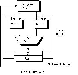
Figure the ALU with register forwarding
y x
i1 1 2 3 4 5
x
i2 1 2 3 4 5
i1 at EX (y), the result is already available. Bypass unit check
if the result is in the buffer then select to use that result instead of
reading from register file. This based on assumption that i1 EX produce
a result at the front half of clock cycle and i2 OF read operand at the
back half.
How deep is the buffer in bypass unit? consider a sequence of instructions
i1 R1 = R2 + R3
i2 R4 = R1 - R5
i3 R6 = R1 + R7
i4 R8 = R1 - R9
y x
i1 1 2 3 4 5
x
i2 1 2 3 4 5
x
i3 1 2 3 4 5
i4 1 2 3 4 5
with bypass unit, i1 only affect i2. There is also hazard between
i1 and i3, to forward the result from i1 to i3 required a buffer of depth
two. There is no hazard between i1 and i4.
To improve stall caused by control hazard,
1 prefetch both next and target addresses
2 use branch prediction
3 delay branch
Branch prediction
use history of branch to predict the current branch (taken/not taken).
The history is stored in "branch-target buffer".
PC of the instruction to be fetched
v
address , predicted branch address, history bit
with one bit of history the rule to decide is simply :
if the previous branch is taken then fetch
from this branch target
This prediction will be wrong twice, one when enter the loop and the
other when leave the loop. To improve the prediction, one can increase
the state of history bit. Example, use 2 bits history with four states.
The rule can be :
if wrong prediction twice then change
prediction to the other way.
Branch-target-buffer
We need to know what address to fetch by the end of Fetch stage.
That is, we need to know what next PC should be (even the newly fetch instruction
is not yet decoded, so we don't even know if that instruction is a branch
or not). Therefore we are predicting the next instruction address
and will send it out (next Fetch) before decoding the instruction.
If the instruction is a branch and we know what the next PC is, we can
have zero stall on branch.
The main idea is to use a cache memory to store : PC of instruction
Fetched and its predicted next PC and history bit. The steps are
as follows:
Figure Steps in handling branch prediction
The history bit says whethere the branch was recently taken or not.
Using one-bit history will predict incorrectly twice in a situation such
as when a branch is almost always taken (such as loop back) and then when
it is not taken (end of loop). Using two-bit, a prediction must miss
twice in a row before it is changed.
Figure Two-bit prediction
Delay branch
The principle of this method is to use the stall cycle to do useful
work. By moving some instruction to be executed in the stall cycle.
The jump instruction is "delayed" i.e. caused the actual jump by some amount
of clock (equal to stall cycle). Some instruction can be scheduled
to be executed in that "delay slot". The instruction can be taken
:
1 from above
2 from target
3 from fall through
from above :
i1
jmp i2
jmp i2 <i1 >
< >
i2
i2
from target :
i1
i2
i2
jmp i2
jmp i1 <i1>
< >
i3
i3
from fall through :
i1
i1
jmp i3 jmp i3
< >
< i2 >
i2
i3
i3
using from target, branch taken should be of high probability.
Using from fall through, branch not taken is of high probability. The instruction
in delay slot must be "safe", that is, when the prediction is wrong, executing
this instruction should not change the machine state until the outcome
of branch is definitely known ( and hence knowing whether this instruction
must be executed or not).
One delay slot can be filled with useful instruction about 50% of the
time. The rest can be filled with NOP.
Example pipeline S1