2110264 Digital Design and
Verification Lab 2009
Principle Lecturer: Setha
Pan-ngum room 13 floor
18 Engineering building 4. tel 02 2186982
Co-ordinator: Prabhas Chongstitvatana prabhas at
chula dot ac dot th room 13 floor 18 Engineering building
4. tel 02 2186982
Announcement
17 Nov 2009 Students are required to
present their design documents before entering the lab session.
Teaching Assistances will verify that students have done their
preparation before entering the lab. Failure to produce a
satisfactory work may result in a prohibition to work in the lab of
that week.
2 Dec 2009 IEEE
CPU simulator contest -- a new webpage is created to
communicate this event to students. Students who want to
participate please form the team (3-5 members, all undergrad., any
department) and register by 11 Jan 2010. The project date is 9
April 2010
Hardware Description Language
no content availble
Small Embedded Systems
The second half of the semester will be based on the experiments with a
microcontroller interfacing to the real world. (such as sensors,
signals and sound). Students are expected to do some wiring to connect
a microcontroller to external devices and do assembly language
programming to perform the experiments.
The goals are to do:
1) understanding a modern microcontroller
2) connect it to some small input/output device (electronics
skill)
3) program it in assembly language to perform simple task such as
display some message on LCD screen
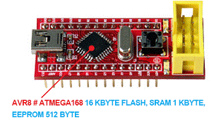
This semester, the second part of the experiment uses AVR
microcontroller (www.atmel.com), the device ATmega168. The
experimental board is one chip that can be mounted on students'
peforated board from the last semester. This small board (called
dual-inline-package, or DIP) can be programmed directly from a USB
port. Here is the picture of the board:

AVR microcontroller
This is a summary of its characteristic:
8 bits data path
modified Harvard architecture: (separate code and data bus)
However, Code Segment can be read by a special instruction (LPM
load program memory)
program is stored in Flash memory and EEPROM (electrically erasable
memory)
EEPROM is not in the address space, it is an external device, accessing
it with a pointer register, therefore it is slow. It has the life time
of approx. 100,000 write cycles.
2 stages pipeline: fetch-execute
address space: registers, I/O, SRAM (static RAM)
32
registers
at address 0..1f (hex)
64
I/O
20..5f
SRAM
60...
registers: R0..R15, R16..R31 , X,Y,Z pointers
performance 1 MIPS/MHz (million instructions)
at clock 20 MHz
operations on registers 1
cycles
ld/st from memory 2
cycles
branch
3
cycles
embedded functions
GPIO general purpose I/O,
bidirectional, built-in pull up resistors.
Timers, PWM (pulse width modulation), 10..12 bits A/D 16x, 12 bits D/A,
bus: i2c, UART (serial), SPI, USI
watch dog (to restart processors), brown out (detect low volt supply),
CAN, USB, Ethernet, DMA (direct memory access), AES (encryption unit).
AVR CPU block diagram (from the data sheet ATmega168)
ATmega168 has 16KBytes Flash, 512 bytes EEPROM, 1K
Bytes SRAM
Here is the short data sheet (with
Instruction Set summary) (500K)
AVR Instruction Set (Full
manual ) (1M)
How to write assembly language for an AVR microcontroller
(coming soon)
last update 1 Dec 2009


