An embedded system with interrupts is presented here:
S21 with interrupt specification
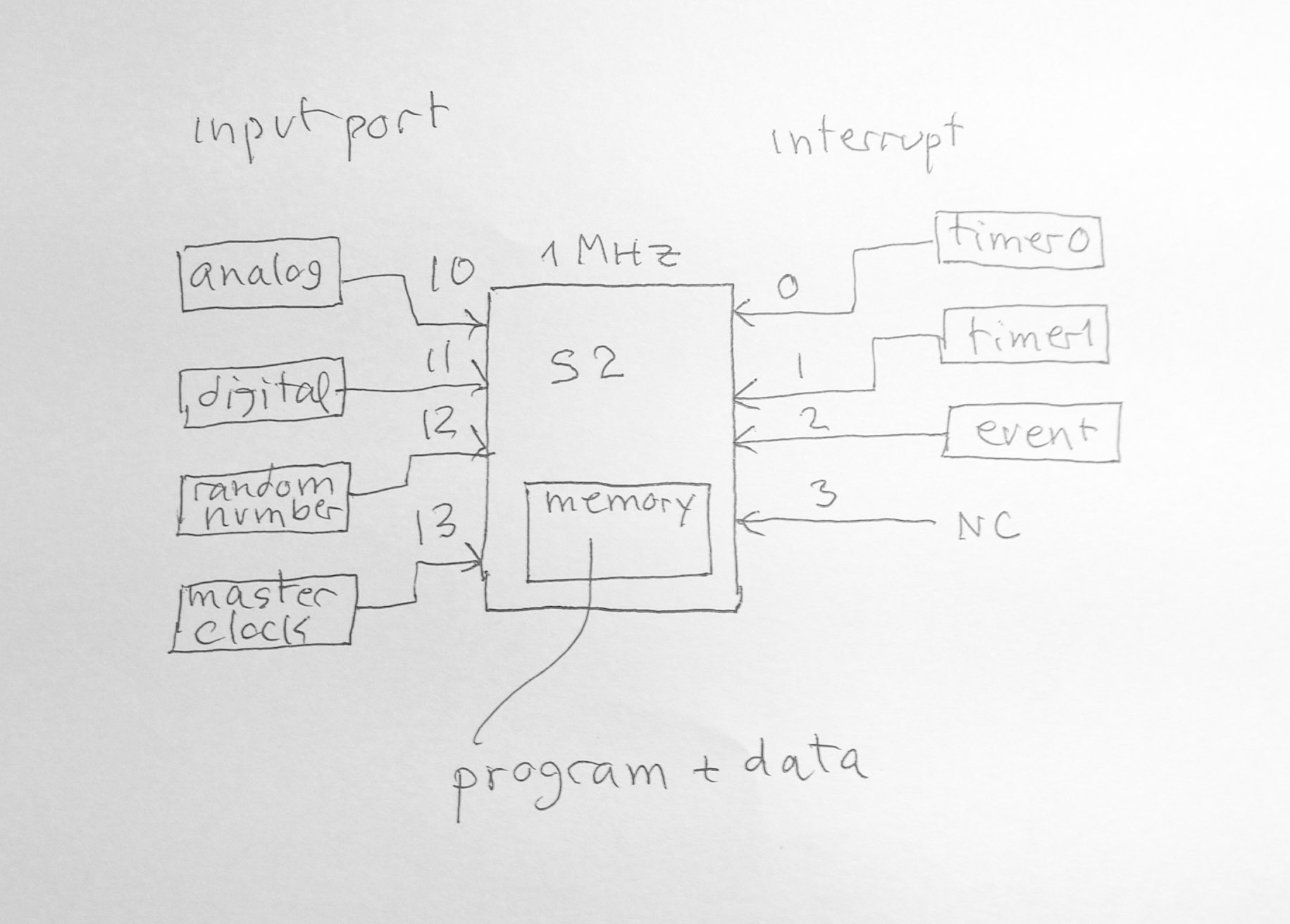
Extension of S21 for IoT board
The main module contains S2.1 processor with memory. The board has four interrupts (int0, int1, int2, int3) and four input ports (10, 11, 12, 13). I made a set of tools for practicing with this kind of programming. The tool consists of the compiler, the assembler and the simulator of the processor (S2.1 processor). The language I used can be found here (Rz language). The interrupt program looks like this:
// simple interrupt // a simple loop run for 10000 inst.
// when interrupt occurs, it prints out cnt
cnt // global counter
int0()
print(cnt," ")
cnt = cnt + 1
main()
cnt = 0
while( 1 ) // wait for int
doze() // sleep and wait for interruptThis program has an empty main loop. It waits for interrupt. The interrupt service routine increments a counter and print it out. The simulation runs for 1 second, or 1,000,000 time unit at the speed of the processor 1MHz. The sequence of commands to run the experiment is, compile the program (simple-int.txt), assemble the assembly file, run the simulator. The output of compiler will be an assembly language file (simple-int-s.txt). This file is assembled into an executable object file (simple-int-s.obj) suitable for the processor simulator.
Here is the console session (assuming you set path to python interpreter appropriately)C:\iot-rz\test>python rz36.pyinput file: simple-int.txt(output simple-int-s.txt)C:\iot-rz\test>python as21.py input file: simple-int-s.txt(output simple-int-s.obj )C:\iot-rz\test>python sim21.pyinput file:simple-int-s.objload program, last address 37
int 201
<0> int 402
<1> int 603
<2> int 804
. . .
<94> int 19296
<95> int 19497
<96> int 19698
<97> int 19899
<98> stop, clock 20000, execute 1897 instructions
C:\iot-rz\test>
ei(n)   // n
      0,1,2,3

di(n) // n 0,1,2,3 settimer0(k) // equivalent
to mov r1 #k, trap r1 #13
settimer1(k) // equivalent
to mov r1 #k, trap r1 #14x = readport(m) // m 10,11,12,13int0()
x = readport(10)
print(x)
main()
while(1)
doze() // sleep and wait
for interruptint0()
x = readport(12)
y = x - ((x / 256) * 256) // modulo 256
print(y)
main()
settimer0(200)
// set timer0 to 200
while(1)
doze()
For analog (and also digital) port, the simulator creates "wave" table
of a fixed period (1,000). You can visualise that the wave
occurs in "real" time, that is, one sampling point per one instruction
cycle. There is a multiplier to change this period (default to
1). The multiplier will "lenghtening" the period of the wave.
It can be changed (also the amplitude) in the simulator header file
"io.h". The "digital" wave table can be created to be used as the
input data for your application. (you need to modify "gendig()" in
"io.c"). You need to recompile the simulator to change it. The analog port
has the sine wave of period 1000 and amplitude +-50.
The default digital wave is a square wave of amplitude (0,5).

turn-on-pumpt = 0while( t < 10 ) delay(1 sec) t = t + 1turn-off-pump t // global int0() t = t + 1 if( t == 10 ) turn-off-pump disableint()main() settimer(1 sec) turn-on-pump t = 0 while(1) doze()
i = 0while( i < 2 ) x = readwave() if x > 0 then while(1) x = readwave() if x < 0
then // zero cross from + to - t0 =
readclock() break else if x < 0 then while(1) x = readwave() if x > 0 then t1 =
readclock() break i = i + 1
// we now have two zero crossif t1 > t0 then dt = t1 - 10else dt = t0 - t1f = 1 / (2*dt) // compute the
frequency state input next-state action
1 +
2
2 +
2 it is + + ... stay
on 2
2 -
3 zero cross + to -
3 -
3 it is - - ... stay
on 3
3 +
4 zero cross - to +
1 -
5 start -
5 -
5 it is - - ... stay
on 5
5 +
2 goto start of +state // globalt0, t1 // globalint0() x = readwave() // readport(10) if state == 1 if( x > 0 ) then state = 2 else state =
5 else if state == 2 if( x > 0 ) then state = 2 else state = 3 t0 =
readclock() // record time of zero cross + to - else if state == 3 if( x < 0 ) then state = 3 else state = 4 t1 =
readclock() // record time of zero cross - to + else if state == 5 if( x < 0 ) then state = 5 else state = 2main() state = 1 while(1) doze() if state == 4 then dt = t1 - t0 f = 1 /
(2*dt) // compute the
frequency state =
1
// reset for next cycle S21 instructions are extended to include:
int #n          software
      interrupt, xop 24

      ei #n           enable
      interrupt, xop 25

      di #n           disable
      interrupt, xop 26

      reti
      return from interrupt, xop 27

      wfi
      wait for interrupt, xop 28
#n resides in r2 field. It is 5-bit, 0..31 . These instructions are in format-X.
int #n acts the same as physical interrupt. When an interrupt occurs the program will jumps to the address pointed by the interrupt vector stored at M[1000]. int #0 at M[1000], int #1 at M[1001] and so on. The return address from interrupt is stored in R[31]. So, R[31] must not be used for other purpose. reti must be used to return from ISR as it is also enable master interrupt to allow other ISR to run.
ei/di enable/disable the interrupt #n. wfi puts CPU to sleep mode and will wake up when an interrupt occurs (which then will run ISR) then continue to run the next instruction.
sim21 trap functions to support simulation of devices (ports and timers)
0 stopRz 3.6 has the following reserve words to use IoT board
asm(s)
      // insert assembly string into asm source
print() //
print int and constant string "..." printc(c) // print char settimer0(t) settimer1(t) asm("di #n") // diable int
n asm("ei #n") // enable int
n doze()
// sleep wait int x = readport(k) // read iot-board ports x = input() // input returns
stringx = malloc(16) // allocate 16 words from heap